EMAIL SUPPORT
dclessons@dclessons.comLOCATION
USWLAN Design Overview
RF Modeling
The important exercise of RF modeling comprises many tasks, including but not limited to:
Scaling plans:
- Use laser measurement.
- Utilize Google Earth.
- Create AutoCAD plans.
Aligning floors:
Pick alignment points carefully.
Drawing walls and assigning attenuation values:
- Do not use built-in values.
- Measure wall attenuation. Defining requirements areas
AP Placement:
- Use corridors and hallways.
- Do not place APs above ceiling tiles.
- Use drop mounts.
- Mount horizontally. Channel Planning
Channel Planning

Measuring Walls
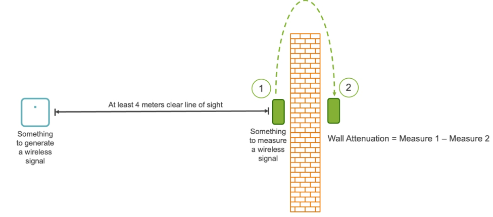
The below figure details a method of measuring the attenuation of a wall. Determining the attenuation of a structure, such as a wall, provides for more accurate modeling.

Channel Contention
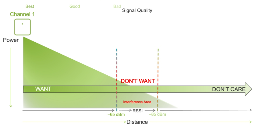
“Want, Don’t Want, Don’t Care” is a general rule for determining how far apart the APs operating on the same channel should be placed. For each AP, you want a signal strength over -65 dBm on the channel that it is assigned. This is considered the “Want” zone.

In the area surrounding this AP, if the received signal strength indicator (RSSI) is between –65 dBm and –85 dBm, placing another AP in this area on the same channel will cause co-channel contention. This is a state that causes stations to share airtime with one another and should be avoided. This is known as the “Don’t Want” zone.


LEAVE A COMMENT
Please login here to comment.