EMAIL SUPPORT
dclessons@dclessons.comLOCATION
USLAB Implement TLOC Extensions
Task :
- Deploy a TLOC extension at Branch 1.
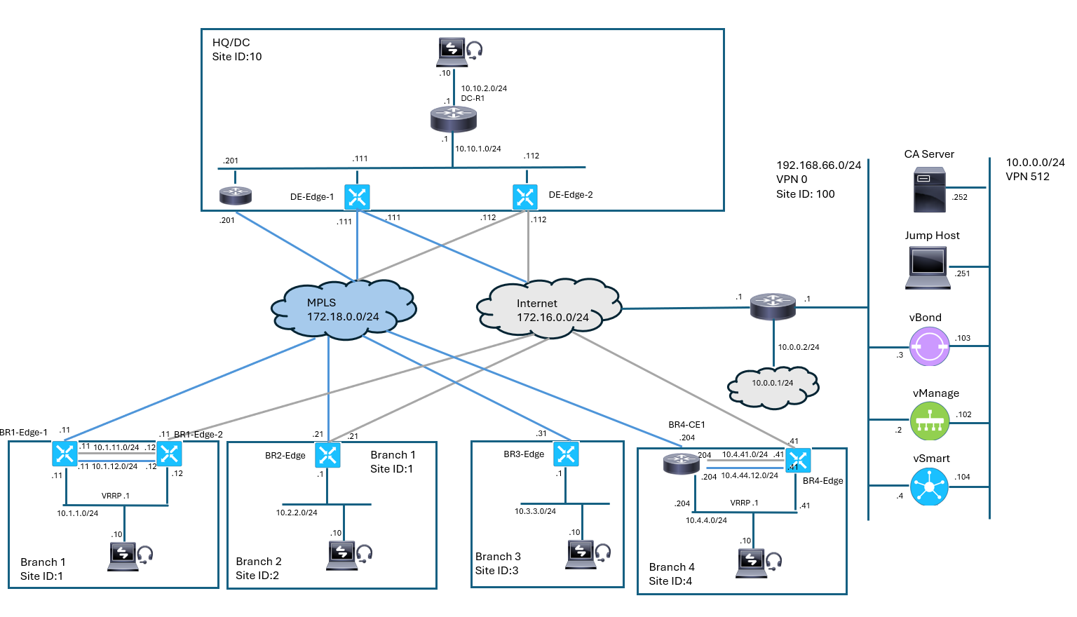
- Branch 1 has two WAN Edge routers: BR1-Edge1 connected to the MPLS transport and BR1-Edge2 connected to the internet transport.
- The TLOC extension will allow BR1-Edge1 to access the internet transport and allow BR1-Edge2 to access the MPLS transport.
Topology :
Solution:
Configure TLOC Extension and Tunnel Interfaces
- Site 1 is deployed with two WAN Edge routers with a single transport connected to each router.
- BR1-Edge1 connects to the MPLS transport, while BR1-Edge2 connects to the internet (biz-internet) transport.
- In this task, you will modify the configuration group assigned to Site 1 routers. You will add and configure a TLOC extension interface and a secondary transport interface.
- You will also configure an additional default route in VPN 0 pointing to the TLOC extension peer and enable Network Address Translation (NAT) on the biz-internet interface on BR1-Edge2 to provide for return traffic routing from the transports to the TLOC extended tunnel interfaces.
- You will not enable NAT on the MPLS interface on the BR1-Edge1 router because this is a “private” transport color and NAT does not resolve the issue. The MPLS transport has a route to the 10.1.12.0/24 pointing to the 172.18.0.11 as the next hop.
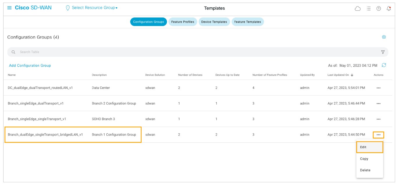
Step1: In Cisco vManage, check the number of tunnels in the SD-WAN fabric and then navigate to Configuration > Templates.
Open the Branch 1 configuration group for editing. Open the Actions menu for the Branch 1 configuration group and choose Edit.
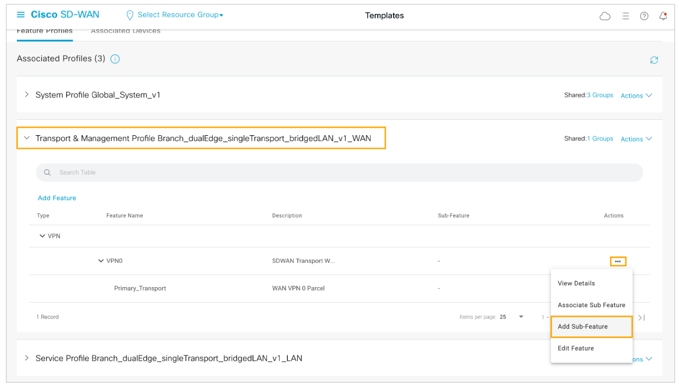
Step 2: Add a new sub-feature to the transport VPN 0. Expand the Transport & Management Profile section and from the Actions menu for VPN 0 choose Add Sub-Feature.
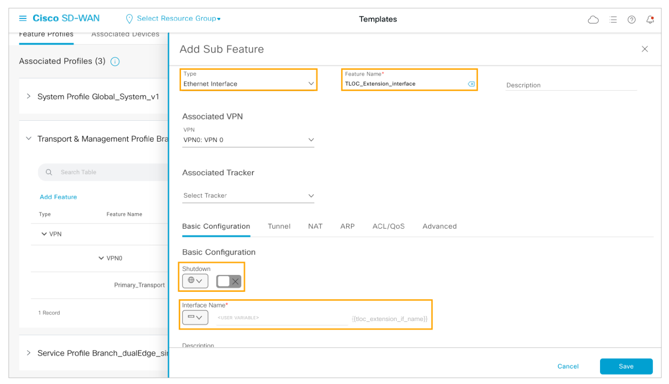
Step 3: Add an Ethernet Interface which will be used for the TLOC extension. Enable the interface and configure the interface name as a device-specific variable.
From the Type drop-down menu choose Ethernet Interface and configure the feature as follows:
-
Feature Name: TLOC_Extension_Interface
-
Shutdown (Global): False
-
Interface Name (Device Specific): tloc_extension_if_name
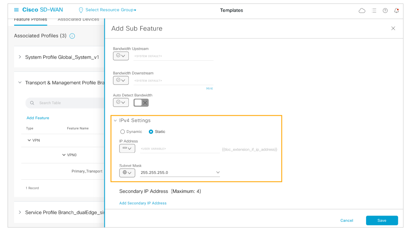
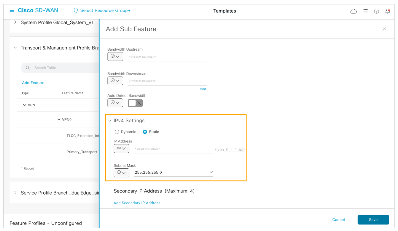
Step 4: Scroll down the Basic Configuration page and expand the IPv4 Settings. Configure the IPv4 Settings as follows:
-
Type: Static
-
IP Address (Device Specific): tloc_extension_if_ip_address
-
Subnet Mask (Global): 255.255.255.0
Step 5: Enable TLOC Extension by configuring the outbound interface name variable under the Advanced tab and Save the sub-feature.
Open the Advanced tab of the Ethernet Interface sub-feature.
Scroll down and configure TLOC Extension as a device-specific variable with a name of tloc_extension_outbound_if_name. Click Save to submit the changes.
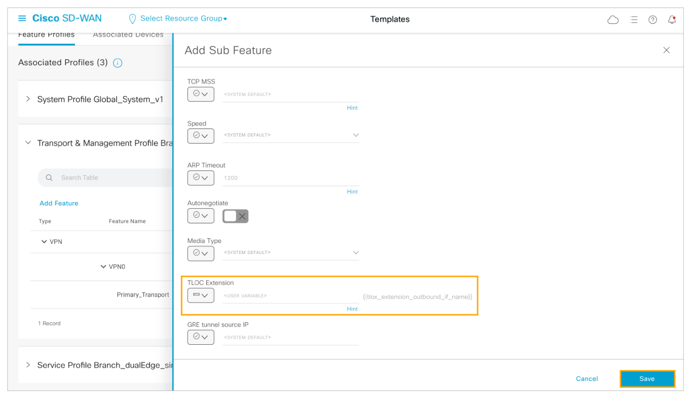
The outbound interface name will be provided during deployment. On BR1-Edge1, the outbound interface is GigabitEthernet2 connected to the MPLS transport. On BR1-Edge2, the outbound interface is GigabitEthernet3 connected to the internet (biz-internet) transport.
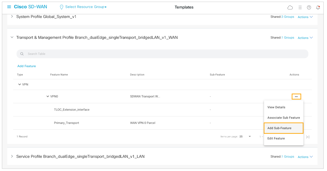
Step 6: Once the TLOC_Extension_Interface is added, add another sub-feature to the transport VPN 0.
Open the VPN0 Actions menu and choose Add Sub-Feature.
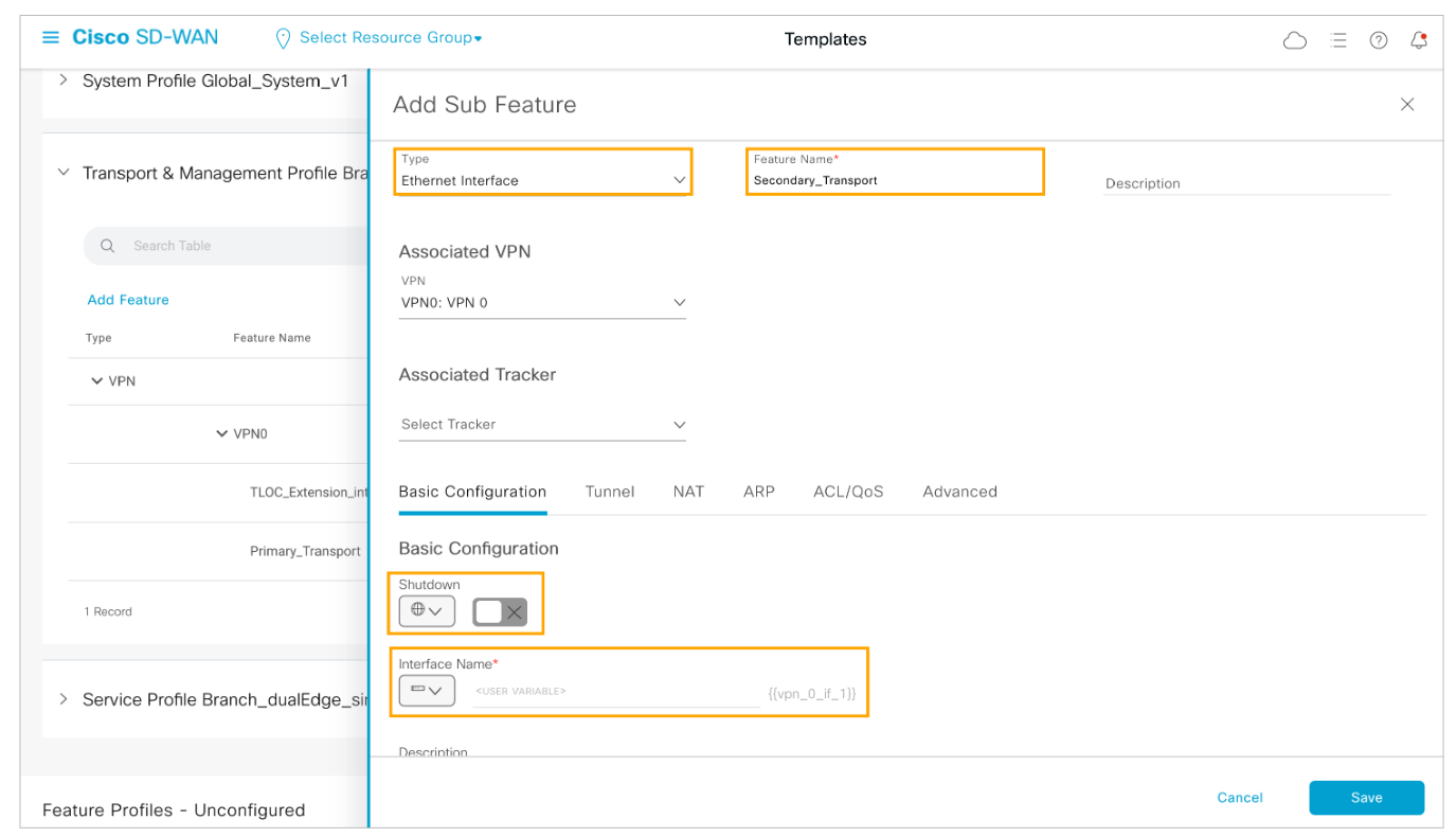
Step 7: Configure the secondary transport Ethernet interface. Enable the interface and configure the interface name as a device-specific variable.
From the Type drop-down menu choose Ethernet Interface and configure the feature as follows:
-
Feature Name: Secondary_Transport
-
Shutdown (Global): False
-
Interface Name (Device Specific): vpn_0_if_1
Step 8: Configure the interface IPv4 settings. Configure the IP Address as a device-specific variable and the subnet mask as 255.255.255.0.
Scroll down the Basic Configuration page and expand the IPv4 Settings. Configure the IPv4 Settings as follows:
-
Type: Static
-
IP Address (Device Specific): vpn_0_if_1_ip
-
Subnet Mask (Global): 255.255.255.0
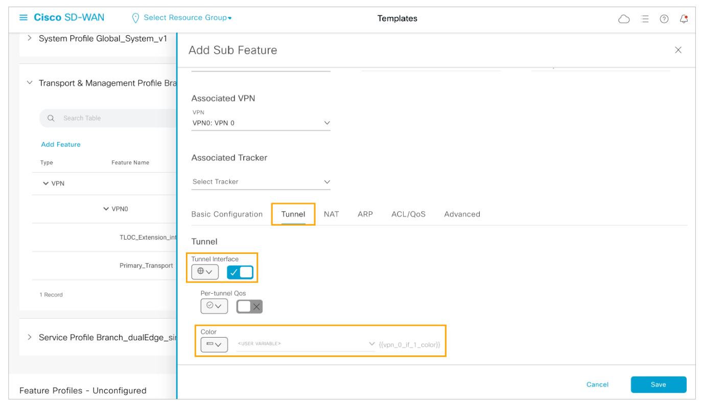
Step 9 : Enable the Tunnel Interface on the secondary transport interface and configure the color as a device-specific variable.
Open the Tunnel tab under the interface settings. Enable the Tunnel Interface and configure the color as a device-specific variable. Name the variable vpn_0_if_1_color.
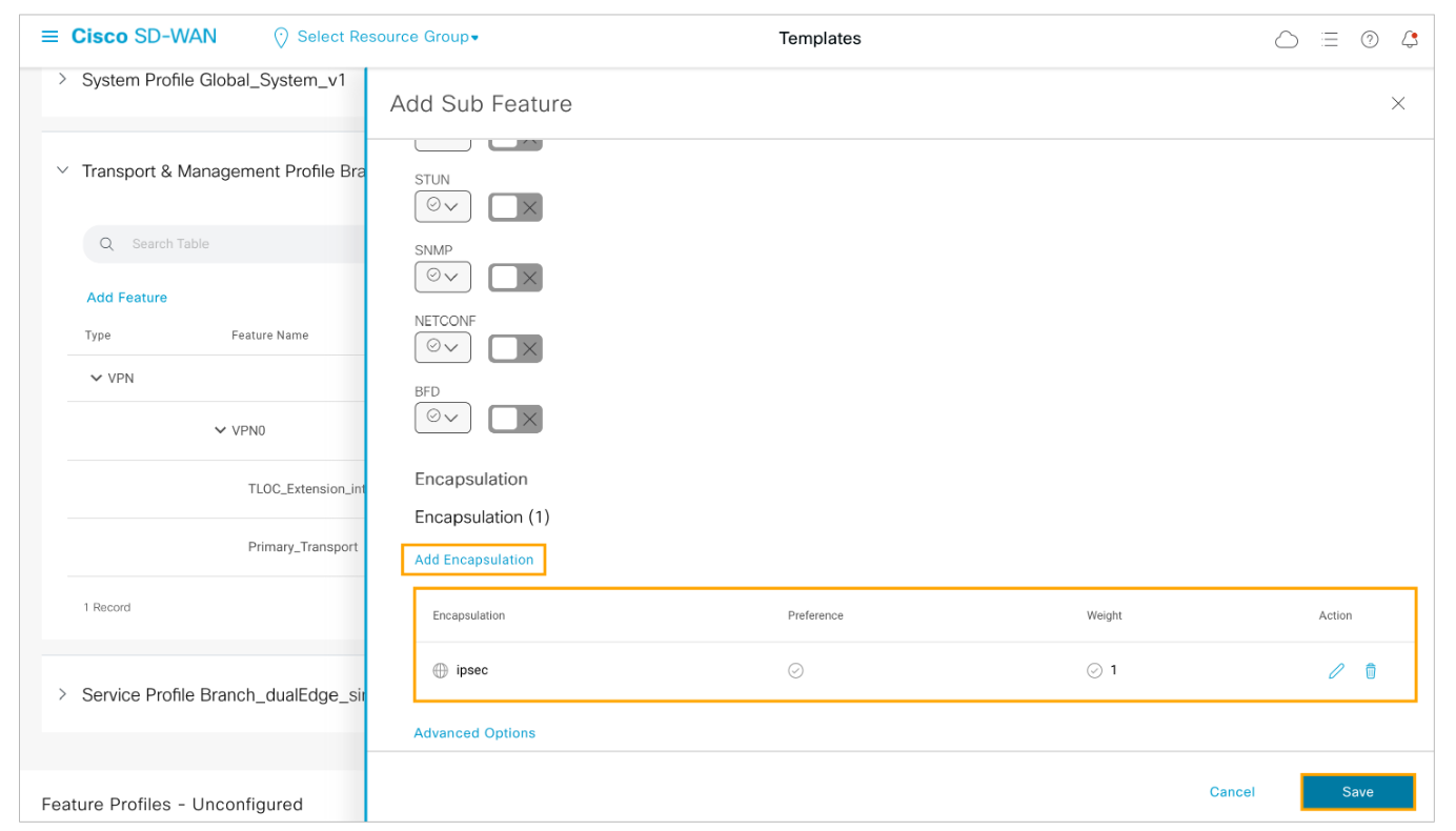
Step 10: Configure IPSec encapsulation for the tunnel interface and save the configuration.
Scroll down to the end of the Tunnel section and configure IPSec Encapsulation for the tunnel interface. Click Add Encapsulation, and select ipsec in the Encapsulation drop-down menu. Leave all other parameters with their values. Click Add and then click Save to submit the changes.
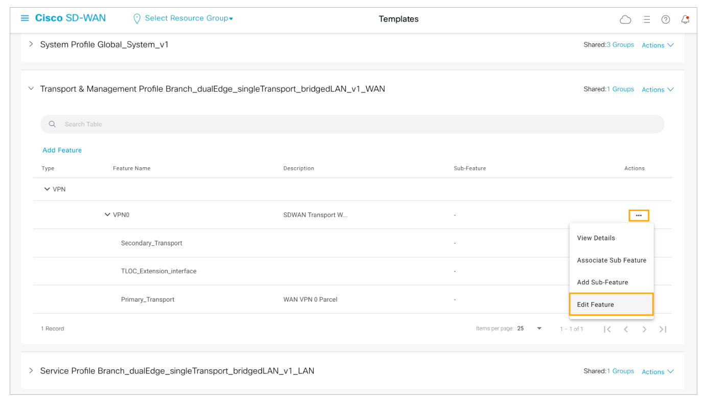
Step 11: Next you must modify the VPN0 feature to add the next hop for the secondary transport.
Under the Transport and Management Profile, Open the Actions menu for the VPN 0 feature and choose Edit Feature.
 Step 12: Open the Route tab and edit the existing default static route. Open the Route tab under the VPN 0 feature and open the existing IPv4 default static route.
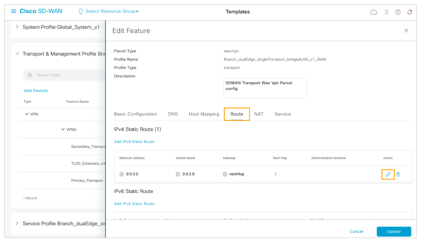
Step 13: Add another next hop for the default static route. Configure it as a device-specific variable for the secondary transport and save the changes to the default route.

Comment
TABLE OF CONTENTS
- Onboarding & Provisioning Configuring Templates
- Authentication between vSmart & vBond
- Authentication between vSmart Controller
- Authentication between vBond & vEdge Router
- Authentication between vEdge Router & vManage NMS
- Authentication between vSmart Controller & vEdge Router
- Viptela Specific Port Terminology
- Deploy & Configure vManage & Generate Certificate
- Deploy & Configure vBond & Generate Certificate
- Deploy & Configure vSmart & Generate Certificate
- Configure vEdge & Generate Certificate
- SDWAN & NAT
- Secure DataPlane Bringup
- Enterprise CA for SDWAN Instances
- ZTP Process & PnP Overview
- Control Plane & Data Plane Operation - Unicast Routing Overview
- Configuring OMP & Its attributes
- Configure Unicast Overlay Routing
- Routing Configuration Example
- Segmentation Overview
- Configuring Segmentation
- Segmentation Configuration Example
- Data Traffic across Private WANs
- NAT in SDWAN & Data Encryption
- SD-WAN Viptela Policy Overview
- SD-WAN Centralized & Localized Control Policy Overview
- SD-WAN Centralized & Localized Data Policy
- Service Chaining
- Traffic Flow Monitoring
- vEdge Router as NAT Device
- Zone Based Firewalls
- Configure Centralized Control Policy
- Configuring Centralized Data Policy
- Configuring Cflowd Traffic Monitoring
- Configuring Zone based Firewall
- Service Chaining Configuration Example
- Configuring Service Side NAT
- Configuring Transport side NAT
- Control Policy Example 1: Hierarchical Topology
- Multi-Region Fabric
- Control Policy Example 2: Implementing Traffic Engineering
- Control Policy Example 2: Dynamic On-Demand Tunnels
- LAB Deploy Cisco SD-WAN Edge Routers
- LAB Deploy SDWAN Controllers
- LAB Deploy Cisco SD-WAN Devices Using Configuration Group
- LAB Implement Service-Side Routing Protocols
- LAB Implement TLOC Extensions
- LAB Implement Control Policies
- LAB Implement Data Policies
- LAB Implement Application-Aware Routing
- LAB Implement Branch and Regional Internet Breakouts
- LAB Migrate Branch Sites
RECENT POSTS
- Installing Context-Aware Network Access Control using Cisco ISE Policies
- Designing Network Access Control that is Scalable using Cisco ISE Architecture
- Enterprise Network Access Control and Policy Enforcement using Cisco ISE
- Secure Device Administration and Network Access Using AAA Architecture
- Designing Enterprise-Class Hybrid Cloud Connectivity Using AWS Networking Services
- Exploring Core AWS Networking and Messaging Concepts for Modern Cloud Architectures
- Understanding Key AWS Services for Modern Cloud Architectures
- Building a Strong AWS Foundation with Amazon S3, EC2, and Virtual Private Cloud
- Understanding the ENSDWI Course: Advanced Cisco SD-WAN (Viptela) Concepts
- A Complete Guide to the DCACI-A Course: Mastering Advanced Cisco ACI Concepts


LEAVE A COMMENT
Please login here to comment.