EMAIL SUPPORT
dclessons@dclessons.comLOCATION
USPBR Topologies & Requirements
The insertion of service nodes in Cisco ACI without PBR typically requires complicated logical topology design such as VRF stitching, so the forwarding table (endpoint table and routing table) points to the service node even when the destination IP/MAC of the packet is not the service node itself.
Service Graph PBR Requirements
When implementing Cisco ACI service graph with PBR you should consider the requirements and design considerations that are applicable to both Layer 1/Layer 2 PBR and Layer 3 PBR, include the following:
- The Cisco ACI fabric must be the gateway for the endpoints and for the PBR node.
- The PBR node bridge domain must belong to the same VRF instance as either the consumer bridge domain (EPG) or provider bridge domain (EPG).
- Multicast and broadcast traffic redirections are not supported, because the contract is applied to unicast traffic only.
- PBR is supposed to be used for IP version 4 (IPv4) and IP version 6 (IPv6) traffic. Thus, a common default filter (Permit All) that includes Address Resolution Protocol (ARP), Ethernet traffic, and other non-IP traffic should not be used for PBR. For example, when configuring PBR between EPGs that are in the same bridge domain, you should not use a Permit All contract filter, because this filter would also redirect ARP traffic to the Layer 4 to Layer 7 device.
- Multinode PBR is supported. The Layer 1/Layer 2/Layer 3 service device can be mixed in a service graph.
- TCAM policy compression (Enable Policy Compression, formerly known as no stats option in the contract filter) does not take effect on a zoning rule with a redirect rule.
The main requirements for the Cisco ACI PBR with inserted service node in routed mode (Layer 3 PBR) are as follows:
- The Layer 4 to Layer 7 device must be deployed in Go-To mode (routed mode).
- Since Cisco APIC release 3.1(x), it is not mandatory to provision service node in a separate bridge domain than the consumer or provider bridge domain (supported on Cisco Nexus 9300-EX and Cisco Nexus 9300-FX platform leaf switches).
- IP data-plane learning should be disabled in the PBR node bridge domain. For releases later than Cisco APIC release 3.1 with Cisco Nexus 9300-EX and -FX platform (or later) leaf switches, data-plane learning is automatically disabled in the PBR node EPG during service graph deployment.
- The administrator must enter the destination of redirection (the IP addresses and MAC addresses of the PBR node interfaces) in the PBR “Layer 3 Destinations” configuration from the Cisco APIC.
- Symmetric PBR (more than one PBR destination per PBR policy) requires Cisco Nexus 9300-EX and -FX platform (or later) leaf switches.
- Some designs and topologies are supported from specific Cisco APIC releases and above, such as PBR usage for more than one node in a service graph and service graph PBR with a contract and vzAny as provider since Cisco APIC release 3.2, service graph PBR with an intra-EPG contract since Cisco APIC release 4.0, and so on.
The main requirements for Cisco ACI with Layer 1/Layer 2 mode device (Layer 1/Layer 2 PBR) are as follows:
- Layer 1/Layer 2 PBR requires Cisco Nexus 9300-EX and -FX platform (or later) leaf switches.
- The Layer 4 to Layer 7 device must be deployed as Layer 1/Layer 2 mode in physical domain (VMM domain is not supported).
- Layer 1/Layer 2 PBR node interfaces must be in a dedicated bridge domain that cannot be shared with other endpoints. These interfaces also cannot be in a Layer 3 outside.
- Only active/standby deployment mode of the service node is supported. Unlike Layer 3 PBR, you cannot deploy service nodes in active/active high-availability mode. In addition, PBR node tracking is mandatory when service nodes are in active/standby mode.
- Layer 1/Layer 2 device must have two interfaces connected to the Cisco ACI fabric (two-arm mode), while the consumer and provider connectors of the Layer 1/Layer 2 device must be in different bridge domains.
- Layer 1/Layer 2 PBR is supported with unmanaged mode service graph only.
- PBR with vzAny or intra-EPG contract is not supported, since these options require service node that is connected with one interface to the Cisco ACI fabric (one-arm mode).
Service Graph PBR Topologies
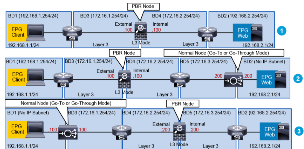
Supported Cisco ACI service graph with PBR configurations in the same VRF instance include the following:

These examples illustrate some of the supported topologies when service node is integrated with the Cisco ACI fabric for the east-west traffic flows between EPG Client (consumer) and EPG Web (provider).
The first example shows the typical use case of one-node firewall insertion, which is in Layer 3 mode, with dedicated bridge domains for PBR node interfaces (mandatory prior to Cisco APIC release 3.1). Hence, the consumer and provider bridge domain, containing the consumer or provider EPG from the contract with service graph PBR, are different from the PBR node bridge domains.


LEAVE A COMMENT
Please login here to comment.