EMAIL SUPPORT
dclessons@dclessons.comLOCATION
USCreating Interface Map
During the design phase, you use logical devices to represent the devices in your network. Remember that logical devices are a great tool to design your network before you even determine the vendor of the equipment that you will use when you finally go to deploy your network. One reason this is possible is because logical devices do not reference any vendor-specific interface-naming conventions.
Instead, logical devices reference a port (port 1, 2, 3. and so on) and a speed (1 Gbps, 10 Gbps, and so on). Another thing to remember is that every device profile represents a unique device type within Apstra. It is the device profile that references the interface-naming convention to be used (ge-0/0/0 for port 1 of chassis, ge-0/0/1 for port 2 of chassis, and so on).
So how do we bridge the gap between the logical device in our design and the interface-naming conventions that exist in the device profiles? It is the interface map that enables you to specify which interfaces in a device profile will map to the ports of logical device. Prior to building your blueprint, you define the interface maps you would like to use. Then, when you go to build your blueprint, you will apply the interface map to specific devices.
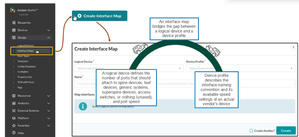
The Create Interface Map Window
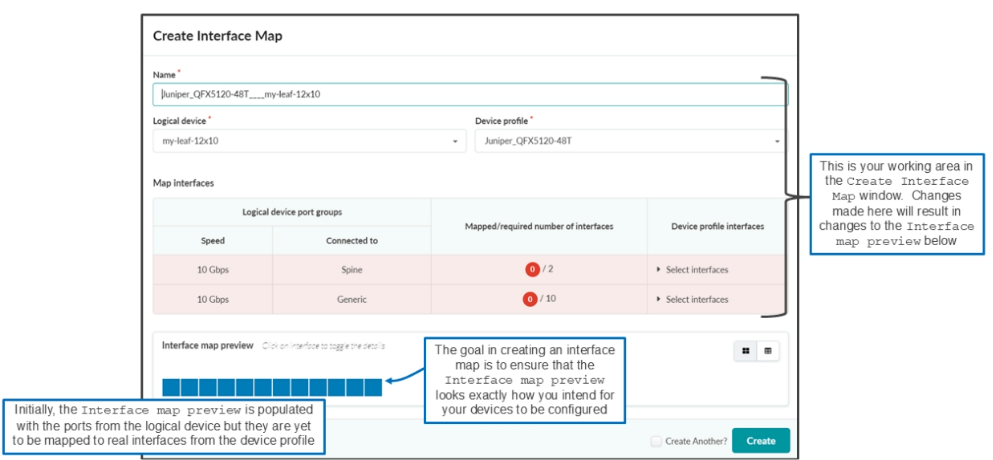
The below figure shows the Create Interface Map window after you have selected the logical device and device profile to be mapped. Your goal in creating the interface map is to ensure that the Interface map preview area of the window looks exactly how you intend it to before clicking Create . In this window, you make selections in the Logical device , Device profile, and Map Interfaces sections, which cause changes to occur in the Interface map preview.
For each interface map, you can select only one logical device and only one device profile. At the moment, everything you see in the window (below the logical device) relates to the selected logical device. You can tell from the details of the window that you configured the my-leaf-12x10 logical device with 12 interfaces at 10 Gbps each. In the logical device, you have assigned 2 interfaces to the Spine port group and 10 interfaces to the Generic port group.
Notice the two red dots. That they are red implies that you must satisfy something before they will turn green. To satisfy the first dot (make it turn green), you must map two interfaces from the device profile to the first two ports of the logical device. To satisfy the second dot, you must map 10 interfaces from the device profile to the last 10 ports of the logical device. We do that in the next few sections.
First Port Group
By clicking Select interfaces, Juniper Apstra software reveals the ports from the device profile. Notice that by hovering over the first port, you can see that the interface name is xe-0/0/0. Notice that you have 53 ports to choose from. You can choose any two ports.

Comment
TABLE OF CONTENTS
- Navigating Apstra UI
- Configure : Logical Devices, Device Profiles, and Interface Maps
- Managing Devices
- Creating Resources and Tags
- Configuring Racks
- Configuring Templates
- Building and Deploying a Blueprint From a Template
- Working With The Active Blueprint
- Enabling Property Sets & Configlets
- Configuring Connectivity Templates
- Configuring Multitenancy
RECENT POSTS
- Installing Context-Aware Network Access Control using Cisco ISE Policies
- Designing Network Access Control that is Scalable using Cisco ISE Architecture
- Enterprise Network Access Control and Policy Enforcement using Cisco ISE
- Secure Device Administration and Network Access Using AAA Architecture
- Designing Enterprise-Class Hybrid Cloud Connectivity Using AWS Networking Services
- Exploring Core AWS Networking and Messaging Concepts for Modern Cloud Architectures
- Understanding Key AWS Services for Modern Cloud Architectures
- Building a Strong AWS Foundation with Amazon S3, EC2, and Virtual Private Cloud
- Understanding the ENSDWI Course: Advanced Cisco SD-WAN (Viptela) Concepts
- A Complete Guide to the DCACI-A Course: Mastering Advanced Cisco ACI Concepts


LEAVE A COMMENT
Please login here to comment.