EMAIL SUPPORT
dclessons@dclessons.comLOCATION
USJuniper Logical Device Overview
Many vendors have devices that have similar form factors. For example, each of the vendors on the slide has a switch that has 32 40GbE ports or a 32x40GbE form factor. Juniper Apstra uses logical devices to represent these form factors during the design process so that customers can design a network without specifying a particular vendor's equipment. This feature enables you to change your design as you see fit and frees you up to not have to choose a vendor until much later.
A logical device represents a future device in your network. But what part of the device does it represent?
- Form factor — As shown on the slide, you configure a logical device to have some ports, each with a specified speed.
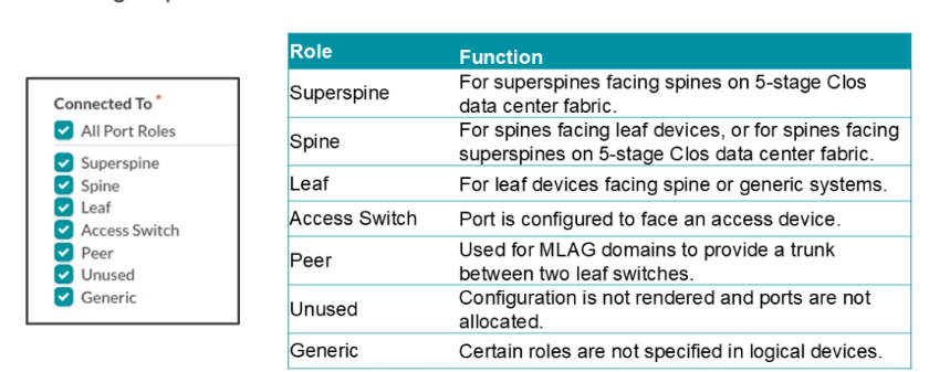
- Port group — You must associate a group of one or more interfaces with a port group. It is here that you specify how numerous ports of this logical device will connect to spine nodes, leaf nodes, Superspine nodes, access switches, or generic systems (servers or external routers, for example).
Port Groups and Roles
When you create a logical device, you assign ports of the logical device to port groups. Port groups are groups of ports that have the same role. You can only use the ports that you place in a port group for the roles associated with the port group. For example, if you place four ports in the port group assigned the Leaf role, then those ports can only connect to leaf nodes. When you create a port group, you may notice that you do not refer to a port by its name (like ge-0/0/0).
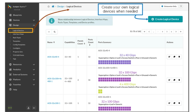
 Logical Device List
Navigate to Design > Logical Devices to see a complete listing of the pre-configured logical devices. If you see one that has the numbers of ports, the speed of ports, and the port group mapping that works for your design, then you can use any of these. However, if you cannot find one that meets the needs of your design (as part of a rack and template), then you can always create your own.
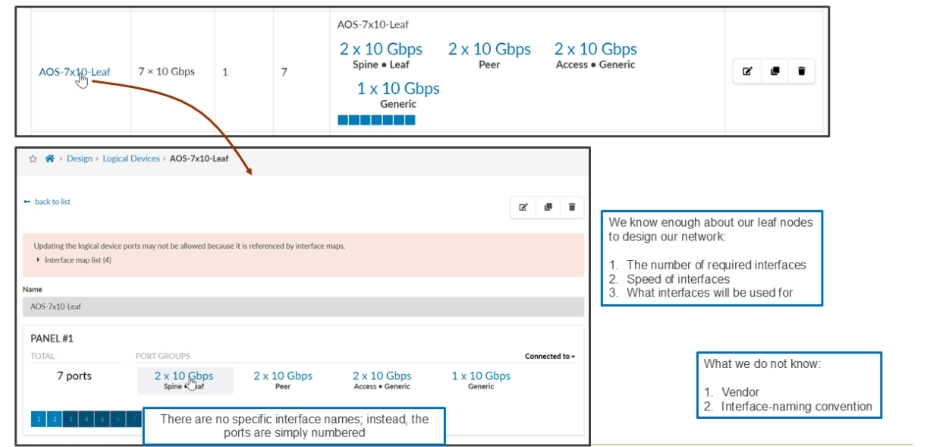
Logical Device Details
Apstra has configured the logical device with the following four port groups.
- Spine/Leaf @ 10Gbps — Ports 1 and 2 of the logical device are expected to be 10GbE ports and you intend for them to be connected to either a spine or leaf node.
- Peer @ 10Gbps — Ports 3 and 4 of the logical device are expected to be 10GbE ports and you intend for them to be connected to a peer device (MLAG peers).
- Access/Generic @ 10Gbps — Ports 5 and 6 of the logical devices are expected to be 10GbE ports and you intend for them to be connected to either an access node or generic system.
- Generic @ 10Gbps — Port 7 of the logical devices are expected to be a 10GbE port and you intend for them to be connected to only a generic system.
Comment
TABLE OF CONTENTS
- Navigating Apstra UI
- Configure : Logical Devices, Device Profiles, and Interface Maps
- Managing Devices
- Creating Resources and Tags
- Configuring Racks
- Configuring Templates
- Building and Deploying a Blueprint From a Template
- Working With The Active Blueprint
- Enabling Property Sets & Configlets
- Configuring Connectivity Templates
- Configuring Multitenancy
RECENT POSTS
- Installing Context-Aware Network Access Control using Cisco ISE Policies
- Designing Network Access Control that is Scalable using Cisco ISE Architecture
- Enterprise Network Access Control and Policy Enforcement using Cisco ISE
- Secure Device Administration and Network Access Using AAA Architecture
- Designing Enterprise-Class Hybrid Cloud Connectivity Using AWS Networking Services
- Exploring Core AWS Networking and Messaging Concepts for Modern Cloud Architectures
- Understanding Key AWS Services for Modern Cloud Architectures
- Building a Strong AWS Foundation with Amazon S3, EC2, and Virtual Private Cloud
- Understanding the ENSDWI Course: Advanced Cisco SD-WAN (Viptela) Concepts
- A Complete Guide to the DCACI-A Course: Mastering Advanced Cisco ACI Concepts


LEAVE A COMMENT
Please login here to comment.