EMAIL SUPPORT
dclessons@dclessons.comLOCATION
USDatacenter Interconnects(DCI)
We can deploy data centers in a variety of areas. We can deploy them within a corporation, the cloud, or in various sites around the globe. Organizations can choose to deploy their own data center, or deploy it in an organization that specializes in data center operations. Whenever we deploy two or more data centers within an organization, there must be a method of connecting them.
A connection between two or more data centers is called a Data Center Interconnect (DCI). A DCI can function at Layer 2 (L2) or Layer 3 (L3). An L2 DCI bridges L2 traffic across the transport network. An L3 DCI connects to more data centers using L3, or IP routing. There are many transport options available to interconnect sites.
Physical Network Options
Before we discuss the protocols and bridging methods that are used to relay traffic from one data center to another, we must discuss the transport network over which data will pass.
Several types of networks can provide DCI functionality:
Point-to-point links are private lines or dark fiber that interconnect sites. These exclusive transport networks are reserved solely for the organization and are not shared with any other entities or customers.
An IP transport network can be a customer-owned or per service provider-owned IP network.
An MPLS interconnect uses multiprotocol label switching to bridge two or more service domains, and can be customer-owned or service provider-owned.
DCI with EVPN-VXLAN
Several methods to deploy EVPN/VXLAN across Data Center Interconnect (DCI).
- Layer 3 VPN (L3VPN) over MPLS
- EVPN stitching
- EVPN-VXLAN over an existing WAN
- Direct connect
Layer 3 DCI
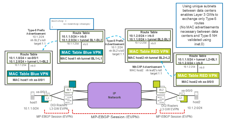
If the IP address range in each data center is unique to that data center, it's unnecessary to advertise media access control (MAC) addresses between data centers. In this scenario, border leaf nodes can advertise IP prefixes in EVPN Type-5 routes. An EVPN Type-5 route does not contain the MAC addresses of the hosts at each data center.
With an L3 DCI, the destinations in the remote data center must be on different subnets than the hosts in the original data center. This means that IP routing must occur. In the example, host1 is on network 10.1.1.0/24. To communicate with hosts in the 10.1.2.0/24 network, host1 must first send its data packets to its default gateway. In the example, the default gateway is the integrated routing and bridging (IRB) interface of the directly connected leaf node, L1.
The L1 device does not operate as a traditional VXLAN L3 gateway. With the traditional VXLAN L3 gateway, we must configure the VXLAN network identifiers (VNIs) to be routed on the L3 gateway devices (each with its own IRB interface). When using Type-5 routes, standard IP routing is used to route between L3 domains. In the example, the data center on the right contains subnet 10.1.2.0/24. L2 learns the MAC address of host2 and then it advertises the MAC as an EVPN Type-2 route to the border leaf node, BL2.
This results in a VXLAN tunnel between BL2 and L2. BL2 installs host2’s MAC address in its switching table, with a next-hop pointing to the tunnel that terminates on L2. Also, BL2 installs the prefix associated with the IRB interface in its route table. The BL2 device advertises the prefix 10.1.2.0/24 to BL1 in an EVPN Type-5 route.
BL1 receives the EVPN Type-5 route, which contains the IP prefix 10.1.2.0/24, and even though it is an EVPN route, it can validate the protocol next-hop of that route using the inet.0 routing table. As an attribute of the Type 5 route received by BL1, BL2 has advertised the MAC address of its IRB interface. BL1 and L1 will use this MAC address as the destination MAC address of the inner most Ethernet frame when forwarding data based on the Type 5 route. BL1 installs the network advertised in the Type 5 route (10.1.2.0/24) in its routing table with a next-hop of the VXLAN tunnel to BL2 and then BL1 advertises the same Type 5 route to its external BGP (EBGP) neighbor, L1. L1 also installs the 10.1.2.0/24 network in its virtual routing and forwarding (VRF) table with a next hop of the VXLAN tunnel to BL2.
When host1 sends traffic to host2, host1 forwards the data to the MAC address of the default gateway on L1's IRB interface. L1 de-encapsulates the VXLAN packet, performs a route lookup on the inner IP header, and looks up the next-hop to host2’s IP address. It determines that the next-hop to the 10.1.2.0/24 network is the VXLAN tunnel between L1 and BL2. L1 encapsulates the data packet in a VXLAN header and forwards it to BL2. BL2 de-encapsulates the VXLAN packet that is destined for its loopback address, analyzes the inner IP header, and identifies host2’s MAC/IP information in the local L2 switching table.
The local L2 switching table shows that the MAC address of host2 is reachable through the tunnel from BL2 to L2. BL2 encapsulates the packet and forwards it through the BL2 to L2 VXLAN tunnel and the packet arrives on L2. L2 de-encapsulates the VXLAN header and forwards the original Ethernet frame to host2.
Layer 2 Stretch
When a Layer 2 stretch is required between data centers, the border leaf nodes advertise EVPN Type-2 routes between the data centers. Since each EVPN Type-2 route represents a single MAC address within a data center, the number of routes advertised across the DCI link could be in the thousands of routes. This means that VXLAN tunnels must exist from end to end across the data centers and the DCI transport network
Layer 3 DCI Example (Signaling Plane)
In the next set of section, we will go through an example of enabling a Layer 3 DCI between two data centers — my-pod13 and my-pod14. The examples will only show the configuration of my-pod13 but note that you must perform matching steps on my-pod14 as well. The figure shows each data center has unique subnets that we are going to route between in the VXLAN overlay and that borderleaf1 and borderleaf2 will act as the EVPN gateways in the scenario.
For the underlay, it is important that the loopback address of the remote EVPN gateway is reachable from all devices in a local data center. For example, it is important that leaf1, spine1, and borderleaf1 all can route packets to borderleaf2. To make this happen, within each data center, each leaf, and border leaf node will have an EBGP peering session with the spine node. To route with the outside world, the border leaf node in each data center will have an EBGP session configured with the External Router (using a connectivity template, not shown in the example figure). Also, to ensure that each router populates the underlay routing table, inet.0, with the correct routing information, each node will redistribute its loopback address as a BGP route. This ensures all devices in all data centers can forward traffic to the loopback address of every device.

Comment
TABLE OF CONTENTS
- Navigating Apstra UI
- Configure : Logical Devices, Device Profiles, and Interface Maps
- Managing Devices
- Creating Resources and Tags
- Configuring Racks
- Configuring Templates
- Building and Deploying a Blueprint From a Template
- Working With The Active Blueprint
- Enabling Property Sets & Configlets
- Configuring Connectivity Templates
- Configuring Multitenancy
RECENT POSTS
- Installing Context-Aware Network Access Control using Cisco ISE Policies
- Designing Network Access Control that is Scalable using Cisco ISE Architecture
- Enterprise Network Access Control and Policy Enforcement using Cisco ISE
- Secure Device Administration and Network Access Using AAA Architecture
- Designing Enterprise-Class Hybrid Cloud Connectivity Using AWS Networking Services
- Exploring Core AWS Networking and Messaging Concepts for Modern Cloud Architectures
- Understanding Key AWS Services for Modern Cloud Architectures
- Building a Strong AWS Foundation with Amazon S3, EC2, and Virtual Private Cloud
- Understanding the ENSDWI Course: Advanced Cisco SD-WAN (Viptela) Concepts
- A Complete Guide to the DCACI-A Course: Mastering Advanced Cisco ACI Concepts


LEAVE A COMMENT
Please login here to comment.