EMAIL SUPPORT
dclessons@dclessons.comLOCATION
USDesigning Rack Phases
During the design phase, you create several reusable building blocks. The building blocks will help you with the automation of deploying an operational data center. Some of these building blocks include:
Resources — These are pools of either IP addresses, autonomous system (AS) numbers, or Virtual Extensible LAN (VXLAN) network identifiers (VNIs). By creating a pool of these values, you can enable Juniper Apstra software to intelligently carve out what it needs to build out your network. For example, by specifying an IP pool and applying that pool to a blueprint, Juniper Apstra will auto-configure the IP addressing for the interfaces that interconnect the spine and leaf nodes.
Logical devices — These are logical representations of spine, leaf, and generic system (servers, external routers, and so on) nodes. You configure the number of ports, the speeds of those ports, and what role they will have (connect to Spine , Leaf , Generic System, or more) in a logical device. You do not, however, have to specify which vendor equipment you will use. This enables you to design your network first without having to settle on the vendor that you will eventually use in the spine, leaf, and superspine positions.
Racks (discussed in this module) — A rack is how you intend for the devices in a rack (leaf nodes and generic systems) to be interconnected. Ideally, you will use a single rack definition to deploy numerous racks that are physically the same.
Templates — In a three-stage fabric, a template is how you intend for your spine nodes to interconnect with the racks (leaf nodes and generic systems). In a five-stage fabric, a template is how you intend to interconnect multiple three-stage fabrics (pods) to the superspine nodes. In a collapsed fabric, a template is how you intend to mesh the connections between leaf nodes as well as interconnect to generic systems.
A Rack Type
Juniper Apstra makes designing your data center easy by enabling you to create a rack design once. With your rack design in place, you can deploy racks based on that design repeatedly.
A rack type is the combination of generic systems and top-of-rack switches. You will use a rack later to build a template. In the template, you will add spine nodes to rows of racks (or superspines to a bunch of three-stage fabrics). You will refer to the rack once in a template and then specify the number of copies of that rack type you intend to use, or you can also use a combination of several rack designs in a single template.
How to Design Rack
You can design your rack in just about any way that you want. You can change your rack designs and even the racks in a running blueprint, with almost no limitations.
You can always use a rack type that specifies just the number of leaf nodes (top-of-rack switches) that it will contain. Later, after you deploy a blueprint (a running IP fabric) using that rack type, you can add generic systems from within the blueprint UI.
You can always add or remove generic systems on the fly from within the blueprint UI.
This method of design works fine as well even if you do not have enough physical generic systems (servers) to connect to the ports of the leaf node you are deploying. The reality of deploying a rack in a blueprint, in this scenario, is that the only thing that gets configured in relation to the generic devices is that Apstra will configure each interface of the leaf node with a description like to-generic_1. Later, to enable communication between the generic system and leaf node, you must configure a connectivity template (covered later in this course). After deploying such a rack in a blueprint, if you realize that one of your servers needs to be multhomed using LAG to the leaf node, you can simply remove two generic systems from the rack in the blueprint and then add the multihomed one.
This is no problem as well. You can always create a rack with one leaf node and then add a leaf node to that rack later. It is also possible to create a rack with two leaf nodes, even though you only physically have one to deploy right now.
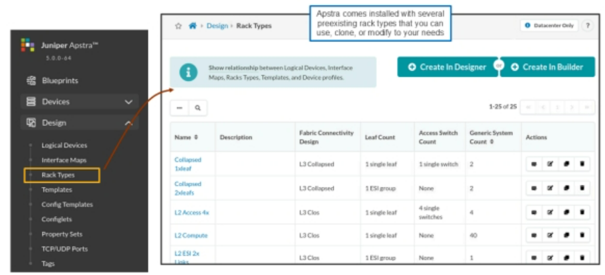
Existing Rack Types
By navigating to Design > Rack Types, you can see existing rack types or even create your own. The predefined racks exist as an example for you. However, you are welcome to use them if they meet your needs, or clone a rack and change the new clone as needed. If you look further into Design > Templates, you notice that many of the predefined rack types are being used to help instantiate the predefined templates
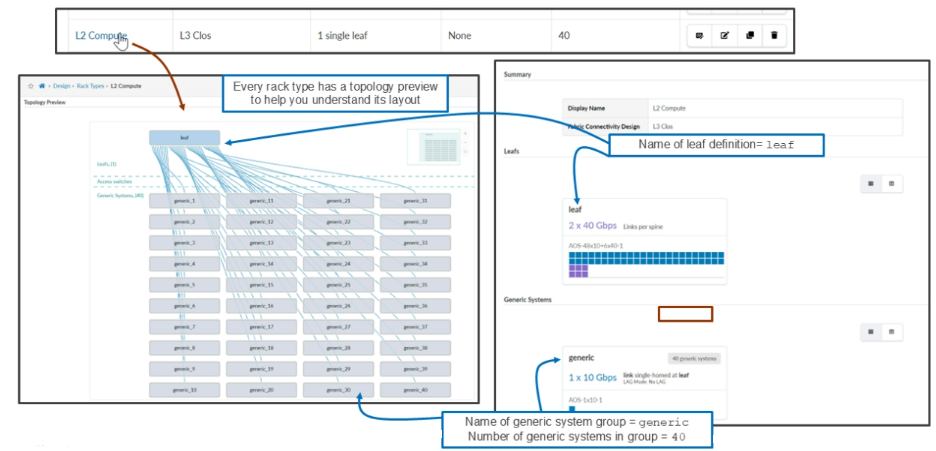
Here, you click the L2 Compute rack type just so you can see what a complete rack type looks like. Every rack type has a Topology Preview section that gives you a visual of what the rack will look like. A rack consists of a Leafs section, an Access section, and a Generic Systems section.
- Leafs — Describes the number of leaf nodes, the speed, and number of links to each spine node, and the logical device associated with the leaf nodes.
- Access — Describes the details of any access switches (standard Ethernet switch, no VXLAN tunnel endpoint [VTEP] functionality) that can be added to the rack.
- Generic Systems — Describes the number of generic systems, the speed and number of links to the leaf, LAG mode of leaf-facing interfaces, and logical devices associated with the generic systems.
Example Topology
The below figure show the step-by-step procedure to create the pictured rack using the rack designer. The rack will comprise two leaf nodes that support ESI LAG redundancy. Also, it will have three generic system groups that each have a single generic system listed.

Comment
TABLE OF CONTENTS
- Navigating Apstra UI
- Configure : Logical Devices, Device Profiles, and Interface Maps
- Managing Devices
- Creating Resources and Tags
- Configuring Racks
- Configuring Templates
- Building and Deploying a Blueprint From a Template
- Working With The Active Blueprint
- Enabling Property Sets & Configlets
- Configuring Connectivity Templates
- Configuring Multitenancy
RECENT POSTS
- Installing Context-Aware Network Access Control using Cisco ISE Policies
- Designing Network Access Control that is Scalable using Cisco ISE Architecture
- Enterprise Network Access Control and Policy Enforcement using Cisco ISE
- Secure Device Administration and Network Access Using AAA Architecture
- Designing Enterprise-Class Hybrid Cloud Connectivity Using AWS Networking Services
- Exploring Core AWS Networking and Messaging Concepts for Modern Cloud Architectures
- Understanding Key AWS Services for Modern Cloud Architectures
- Building a Strong AWS Foundation with Amazon S3, EC2, and Virtual Private Cloud
- Understanding the ENSDWI Course: Advanced Cisco SD-WAN (Viptela) Concepts
- A Complete Guide to the DCACI-A Course: Mastering Advanced Cisco ACI Concepts


LEAVE A COMMENT
Please login here to comment.