EMAIL SUPPORT
dclessons@dclessons.comLOCATION
USPBR in Service Graph - ACI
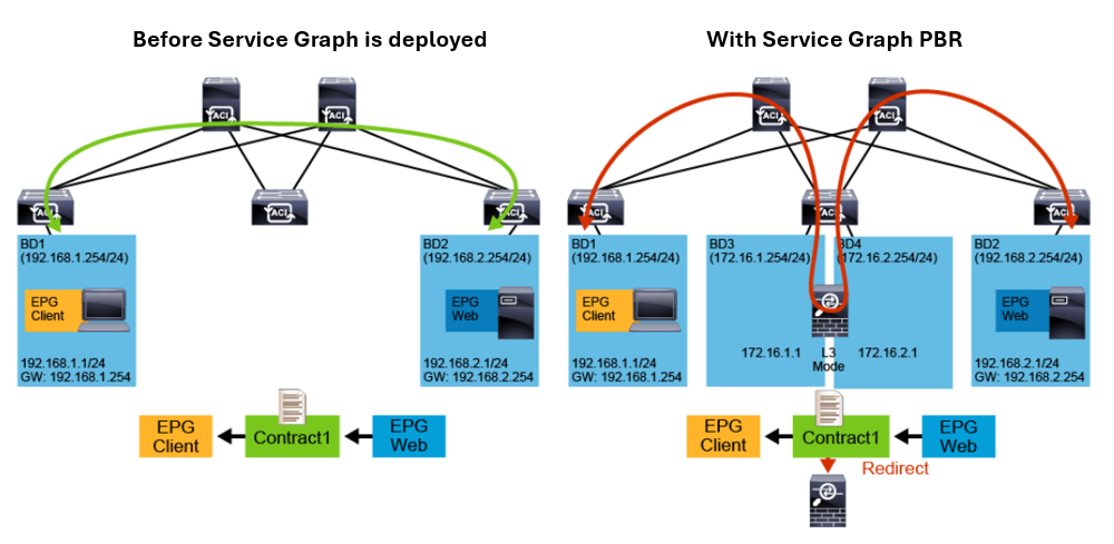
In the Cisco ACI fabric the traffic is routed and bridged based on the destination IP and MAC addresses. You can use service graphs with PBR to redirect traffic and send packets to service nodes connected to the fabric, such as firewall, Cisco Intrusion Prevention System (IPS), or load balancer, while overriding the information available in the forwarding table (endpoint table and RIB).

When the service graph with PBR is used, even though the forwarding table points to the destination endpoint directly, the traffic is redirected to the service node (such as firewall) based on the contract the traffic is hitting. In the contract with the PBR service graph, the traffic redirection is defined towards the service node, which operates in Layer 3 mode and is integrated as service node in the Cisco ACI fabric. It routes and inspects the traffic between the client and server, which is deployed in different EPGs.
PBR with a Service Node in Layer 3 Mode
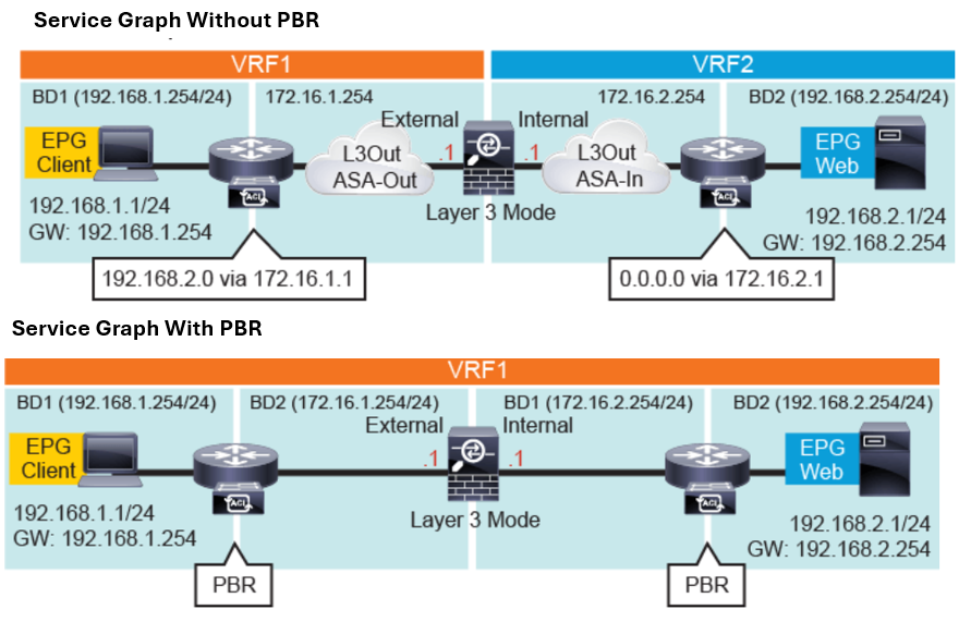
This figure shows the two service graph options for the insertion of a firewall that protects east-west traffic flows between endpoints in the EPG Client and EPG Web. It illustrates the difference between a classic VRF sandwich design (service graph without PBR), and service graph with PBR, using Layer 4 to Layer 7 device deployed in routed mode (referred as Go-To mode).
 The design that uses service graph without PBR requires multiple VRFs (a classic VRF sandwich configuration) and Layer 3 outside peering, which are established between the fabric and the internal and external firewall interfaces. The traffic between the client and web server goes through the firewall, which is a routed Layer 3 hop that has one interface in VRF1 and one interface in VRF 2 instance.


LEAVE A COMMENT
Please login here to comment.