EMAIL SUPPORT
dclessons@dclessons.comLOCATION
USService Graph Tracking
Since Cisco APIC release 2.2(3j) and going forward with Cisco APIC release 3.1(1) (not supported in Cisco APIC release 3.0(x)), a PBR node tracking feature was introduced, which enables you to prevent redirection of traffic to a PBR node that is down. If a PBR node goes down/fails, a specific mechanism, referred as hashing is used, so existing traffic flows are redirected to another node. This feature requires Cisco Nexus 9300-EX or -FX platform (or later) leaf switches.
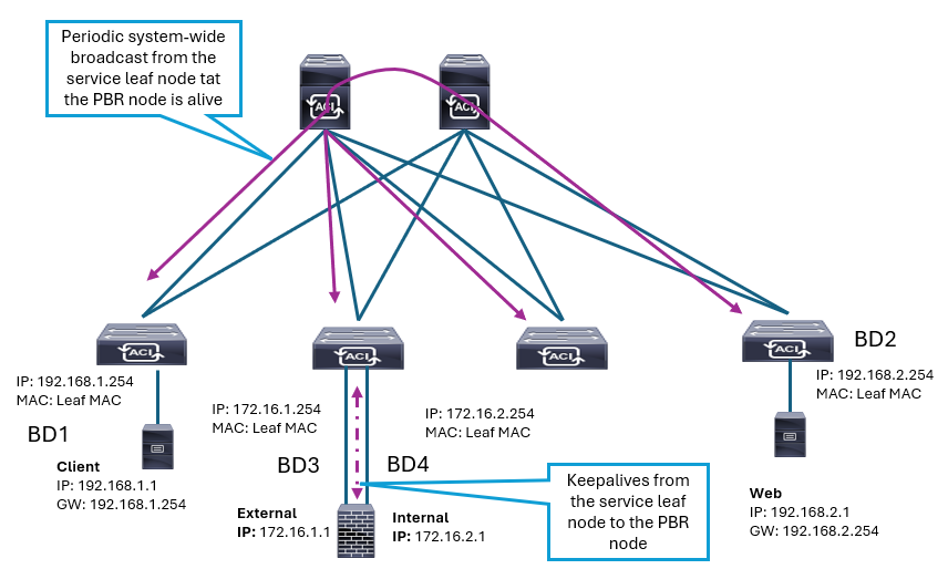
The following figure shows how PBR node tracking functions:
 The tracking option follows this sequence:
-
The service leaf node to which the PBR node is connected periodically sends keepalive messages, using Internet Control Message Protocol (ICMP), or Transmission Control Protocol (TCP) information to the local PBR node.
-
Then, the service leaf node periodically announces availability information to all the other leaf switches through a systemwide broadcast message. This information allows all the leaf nodes to know whether they can still use that specific PBR node when applying the PBR policy locally.
Health Groups
The PBR service node may be unusable for different reasons. For example, the PBR node can be unreachable as a device, or only the consumer or the provider connector of the PBR node can be down. To prevent traffic from being black-holed due to failed interface for the consumer or provider connector, Cisco ACI must avoid using the PBR node for traffic in both directions. Some Layer 4 to Layer 7 devices can bring down an interface if another interface is down or even failover to a backup service node, so you can use this capability on the Layer 4 to Layer 7 device to avoid black-holing. However, if the Layer 4 to Layer 7 device does not have this capability, you should use the Cisco ACI health group feature to completely avoid using the PBR node, if either the consumer or provider connector is down.
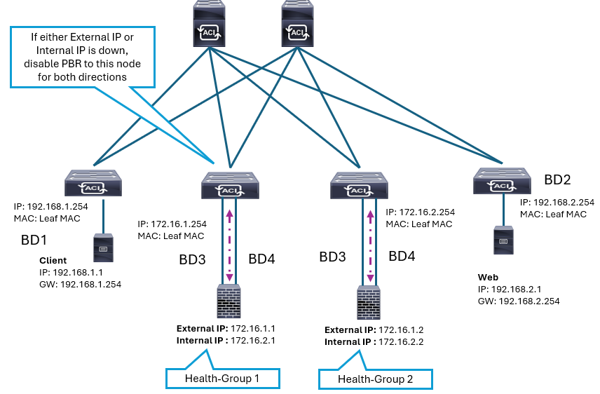
You can use each PBR destination IP and MAC address in a health group. The following figure depicts an example with two PBR nodes that are integrated in a Cisco ACI fabric, while the IP addresses configured on their external and internal interfaces are assigned to two health groups.

In this example, there are two PBR node destinations, which are deployed in two-arm mode. The external and internal interface of the PBR node should be in the same health group, to disable the remaining interface if single interface fails. Hence, FW1 has 172.16.1.1 as the consumer connector and 172.16.2.1 as the provider connector, and are in Health-group 1. FW2 has 172.16.1.2 as the consumer connector and 172.16.2.2 as the provider connector, and are in Health-group 2. If either of the PBR destinations in the same health group is down, that node will not be used for PBR, which avoids black-holing if this node is further utilized.
Threshold
You must make sure that a Layer 4 to Layer 7 device does not become a bottleneck in the network, and that you have enough of available Layer 4 to Layer 7 devices to handle the traffic. If the utilized PBR nodes introduce bottleneck, the PBR action should be automatically disabled.
To determine whether PBR should or should not be enabled, PBR tracking offers configurable minimum and maximum threshold values that are based on the percentage of available PBR destinations in a PBR policy. If the number of available PBR destinations falls below the minimum percentage, the traffic is permitted or dropped rather than redirected, based on the configured down action, such as permit, deny, and bypass. To revert to the original state and redirect the traffic again, the number of available PBR destinations must reach the maximum percentage.
This figure illustrates an example with five PBR destinations with the threshold feature enabled, including 20 percent set as the minimum percentage and 80 percent set as the maximum percentage.


LEAVE A COMMENT
Please login here to comment.