EMAIL SUPPORT
dclessons@dclessons.comLOCATION
USACI Multi-Pod Overview
Cisco ACI Multi-Pod design represents a single Cisco APIC cluster/single domain that interconnects portions of the fabrics (referred as pods) while each one has its own leaf-and-spine architecture.
Why do you need the Cisco ACI Multi-Pod?
- Deployment of active-active disaster recovery solution for business continuity.
- Data center deployed in multiple server rooms.
- Infrastructure for a virtualization solution that supports live VM mobility across Layer 3 domains, etc.
- Use a single administration domain.
The main advantage of the Cisco ACI Multi-Pod design is hence operational simplicity, with separate pods managed as if they were logically a single entity. It enables you to manage all pods from a single point of configuration, while all Cisco ACI building blocks, such as tenants, virtual routing and forwarding (VRF) instances, bridge domains, endpoint groups (EPGs), and so on are deployed and useable on all pods in a Cisco ACI fabric.
The connectivity between pods is established through IP connection between spines in each pod. This IP connection is called Inter-Pod Network (IPN).
The following figure illustrates the Cisco ACI Multi-Pod deployment.
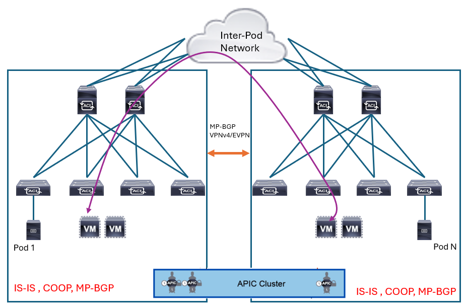 The main infra control plane protocols that run individually in each pod are as follows:
-
Intermediate System-to-Intermediate System (IS-IS): For infra tunnel endpoint (TEP) reachability within a pod.
Even when IS-IS stopped working in one pod, it does not affect IS-IS in other pods because IS-IS runs only between leaf and spine switches in each pod. For TEP reachability towards nodes in other pods, spines learn a TEP range of other pods, instead of individual TEP IPs, via Open Shortest Path First (OSPF) through IPN. This TEP range is advertised to local leaf switches via IS-IS within each pod.
-
Council of Oracles Protocol (COOP): For endpoint information within a pod.
Even when COOP stopped working in one pod, it does not affect COOP in other pods because COOP runs only between leaf and spine switches in each pod. However, endpoint entries in one pod are shared and stored in COOP database in other pods as well via Multiprotocol Border Gateway Protocol (MP-BGP) Ethernet VPN (EVPN) between spine switches in each pod through IPN. Hence, users still need to pay attention to endpoint scalability across a fabric.
-
VPNv4/v6 MP-BGP: For Layer 3 Outside (L3Out) routes distribution within a pod.
Even when MP-BGP stopped working in one pod, it does not affect MP-BGP in other pods because MP-BGP establishes neighbors only between route reflector spine switches and leaf switches in each pod to distribute L3Out routes within a pod. On top of MP-BGP within a pod, Multi-Pod establishes other MP-BGP VPNv4/v6 sessions between spine switches in each pod through IPN. This MP-BGP is called external MP-BGP compared to internal MP-BGP within each pod, which is used to share L3Out routes in one pod to other pods.
There are two main use cases for the deployment of Cisco ACI Multi-Pod regarding physical location of different pods:
-
Multiple pods in the same physical data location: You can use this approach when you have a very large fabric. You can divide it in smaller pods and benefit from the failure domain isolation, and when you have a specific cabling layout already in place inside the data center. Also, you can use Cisco ACI Multi-Pod when there is a need to scale up a single ACI fabric with above 200 leaf nodes in a single pod, which you can divide in multiple pods, following a requirement to create a very large fabric. The latency in the IPN is not a problem in this use case, since the pods are placed in the same physical location.
-
Multiple pods across different locations: Enables you to implement the Cisco ACI Multi-Pod solution between fabrics in different locations. The pods are usually deployed in relative proximity (such as a metropolitan area) and interconnected through point-to-point links (such as dark fiber connections or dense wavelength division multiplexing [DWDM] circuits), or in different geographical locations connected through IPN (which can even be internet) that provides IP reachability, while taking into account the latency between pods, to avoid bottlenecks in the infrastructure.
Based on the use cases described above, Cisco ACI Multi-Pod can be deployed in these topologies:
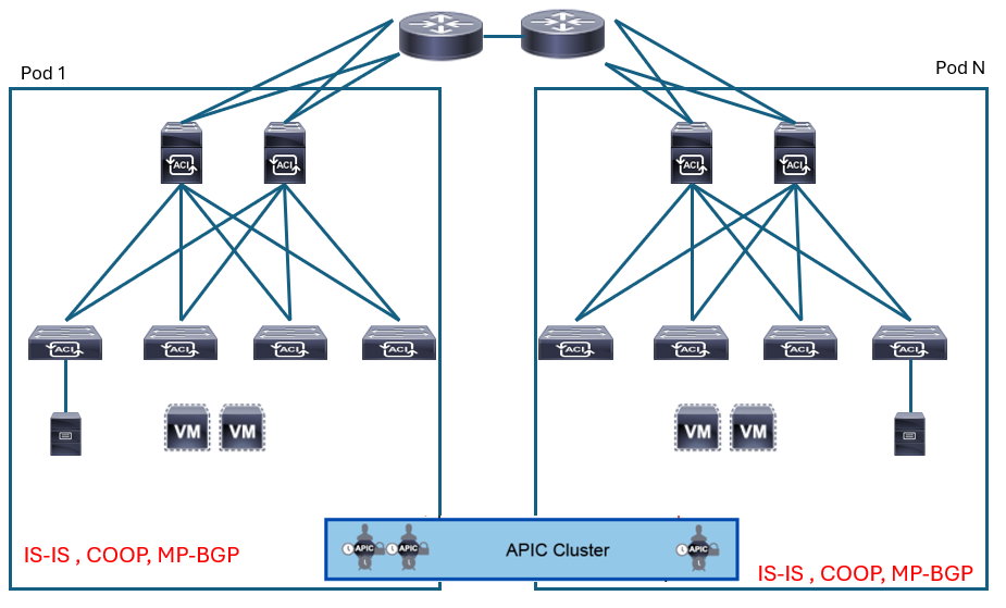
Intra data center: Since the pods are deployed in the same data center, you can use a pair of centralized IPN devices to interconnect the different pods. Those IPN devices must potentially support many 40/100/400G interfaces, so you can utilize a couple of modular switches for this role.
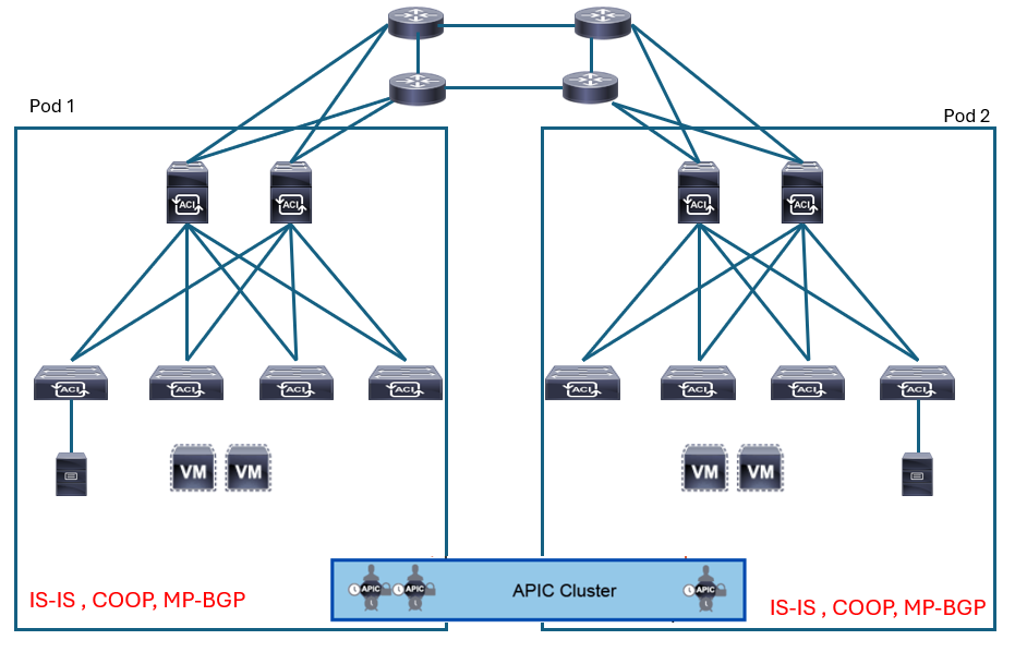
 Two directly connected data centers: The pods are positioned in two data centers in different locations, connected by point-to-point links (dark fibers or DWDM circuits). The maximum supported latency between pods is 50 msec round-trip time (RTT), which roughly translates to a geographical distance of up to 2500 miles (approximately 4000 km). Prior to Cisco ACI Release 2.3(1), the supported latency was 10 msec RTT. Please note that the link between the spine switches and IPN routers is 40/100G because of spine switches, while the interconnecting link between the data centers is typically 10G/40G/100G. Although there are no specific bandwidth requirements between pods, it needs to be designed to accommodate user traffic between pods.
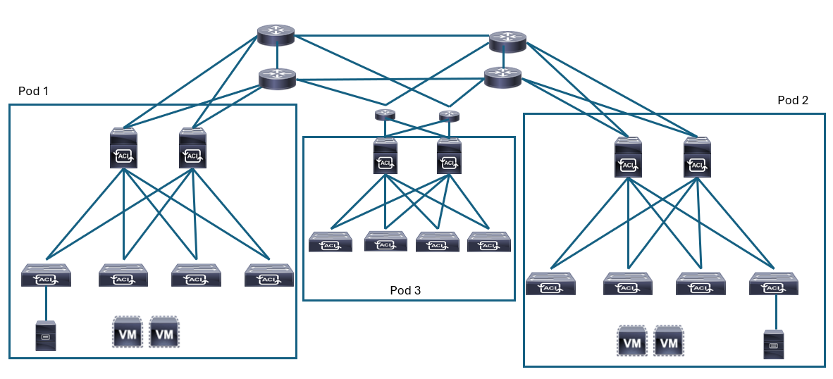
 Three directly connected data centers: The pods are positioned in three data center, directly connected among each other. Similarly, the interconnection can be established through dark fibers or DWDM circuits offering10/40/100/400G speed. The same requirement and considerations from the previous use case applies here.
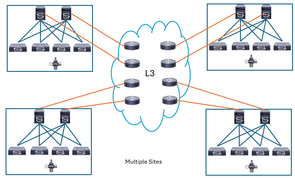
 Multiple sites connected by a generic Layer 3 network: Enables you to connect multiple pods in multiple sites, which are connected by a generic Layer 3 infrastructure (for example, Multiprotocol Label Switching [MPLS] network). The same requirements from previous use cases such as latency apply here as well.
Failure Scenarios
Since the database used by the APIC is split into several database units (shards), while each shard is replicated three times with each copy assigned to a specific Cisco APIC, the Cisco ACI Multi-Pod fabric may face different failure scenarios due to the positioning of the APIC nodes in pods. In a three-node Cisco APIC cluster deployment scenario, one replica for each shard is always available on every Cisco APIC node, but if you use a larger model, for example, a five-node Cisco APIC cluster, the three replicas are spread on three of the five nodes.


LEAVE A COMMENT
Please login here to comment.