EMAIL SUPPORT
dclessons@dclessons.comLOCATION
USLAB 1 How to Validate Fabric Discovery
Topology:
Below Digrams refers the Physical topology of this Lab.
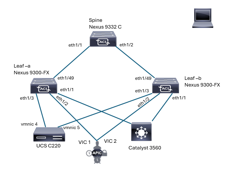
The Cisco Application Centric Infrastructure (ACI) lab topology consists of a Cisco Application Policy Infrastructure Controller (APIC) and three Cisco Nexus 9000 Series Switches. The fabric consists of a spine switch and two leaf switches.
The Cisco APIC out-of-band (OOB) management IP address has already been set to 192.168.11.1.
When a Cisco APIC appliance hardware (which is essentially the same as Cisco UCS C-Series server) boots up for the first time with Cisco APIC OS, a user will be prompted by an interactive Setup Utility on Cisco APIC keyboard, video, mouse (KVM) or virtual keyboard, video, mouse (vKVM) on Cisco APIC Integrated Management Controller (CIMC). In this lab, the Cisco APIC initial setup through Setup Utility has already been performed as a part of the automated lab setup initialization. Bold letters were entered by the automated lab initialization:
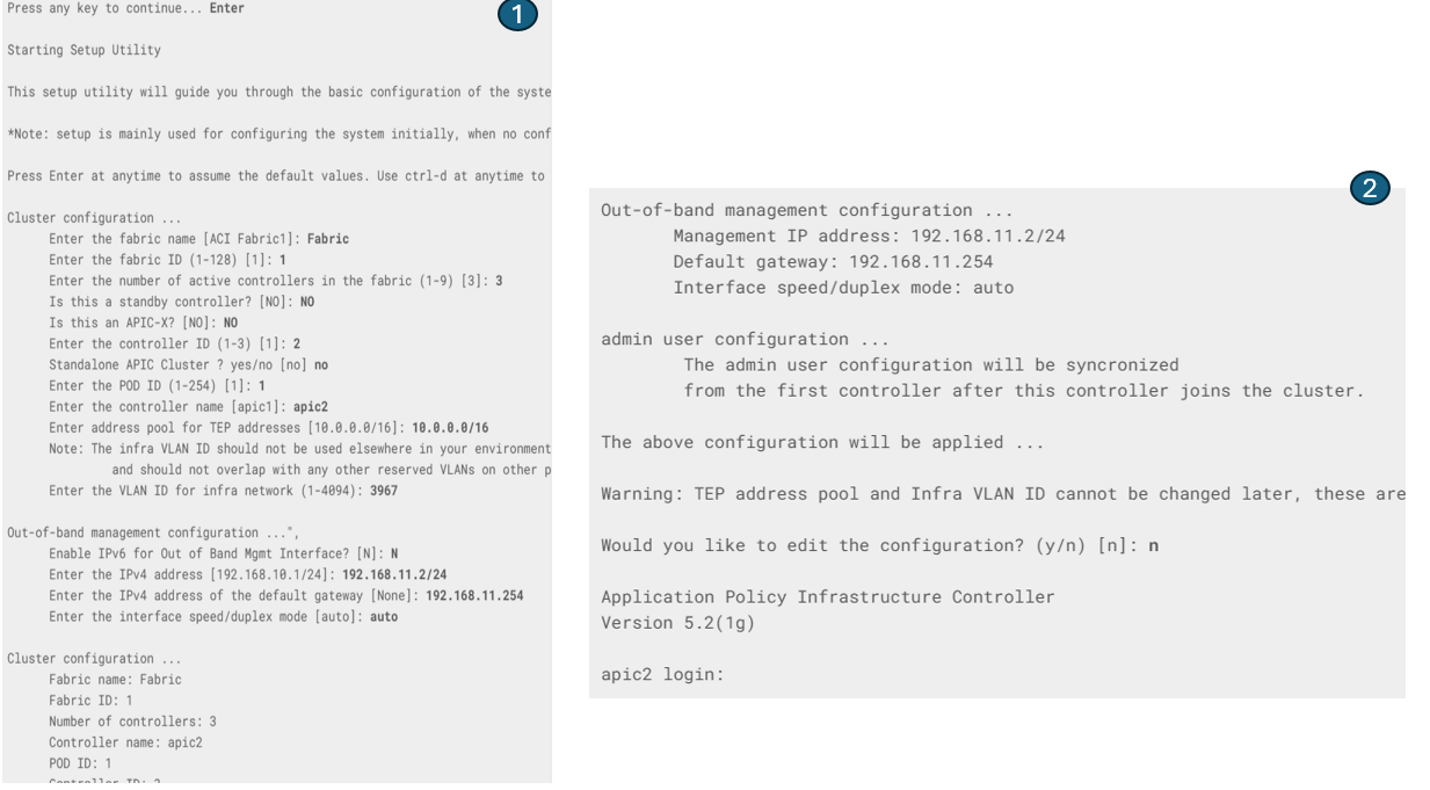
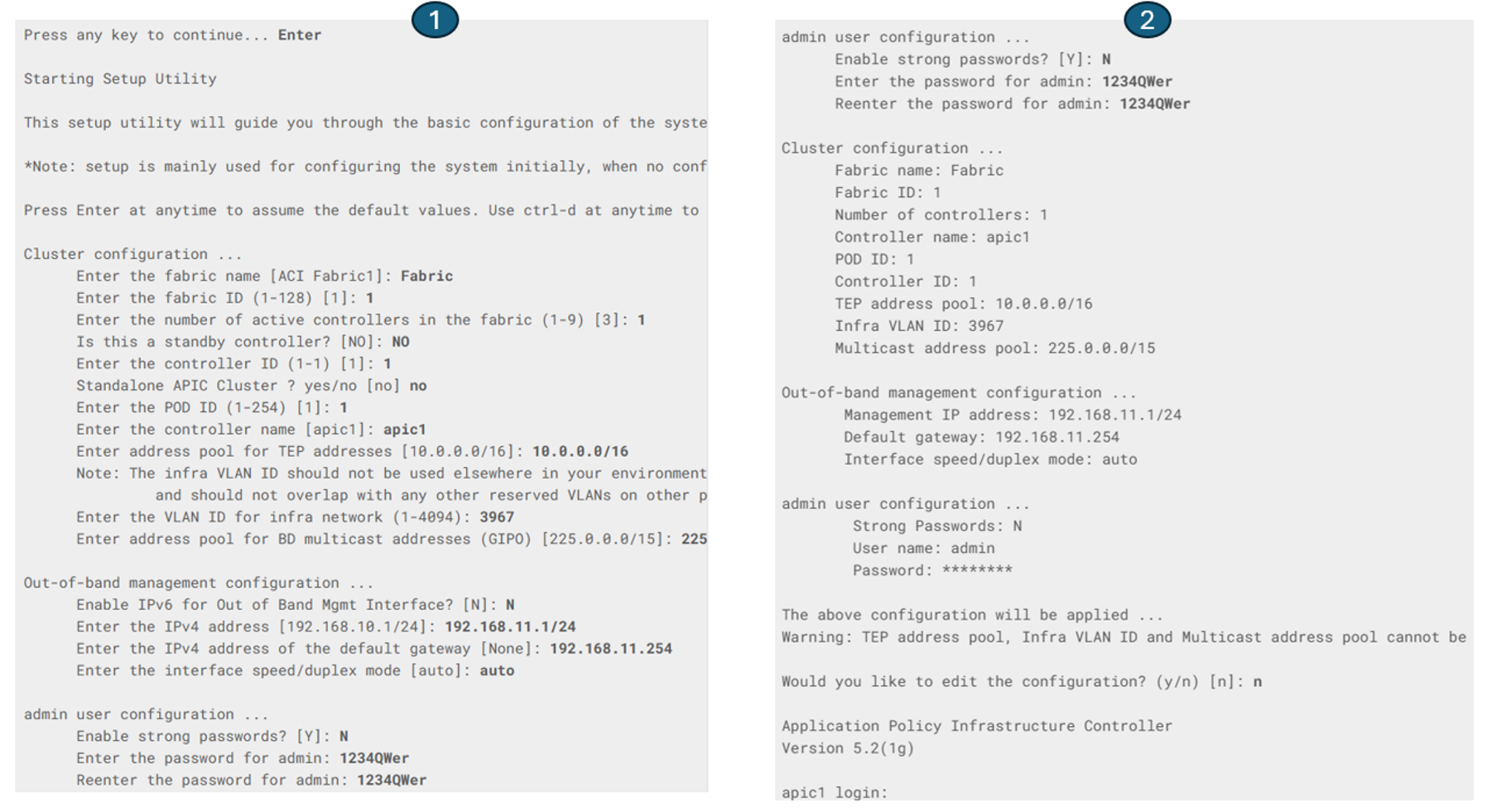 After the first Cisco APIC (apic1) is initialized, all leaf and spine switches can be discovered and registered with a few clicks. If the cluster consisted of more than a single controller, the Setup Utility on the subsequent controllers would require less input, as shown in the below example with three controllers. You would not enter the multicast range and admin credentials. Instead, these parameters are synchronized from apic1 to other Cisco APICs once the cluster is formed correctly.
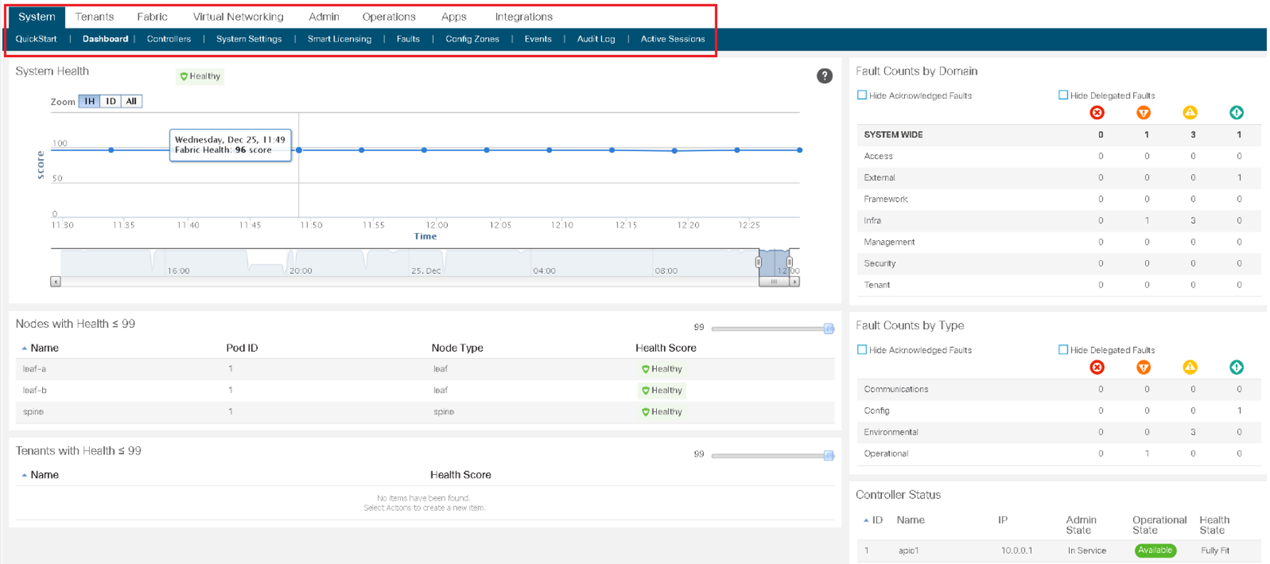
Now Access the APIC from its Management IP with the credentials you have entered via APIC setup.
Examine the top-most portion of the user interface, also referred to as the menu bar (System, Tenants, Fabric, Virtual Networking, Admin, Operations, Apps, Integrations).You will see some alerts, among others about an insufficient number of in-service controllers. The minimum recommended setup for the Cisco APIC is a cluster consisting of three controllers.
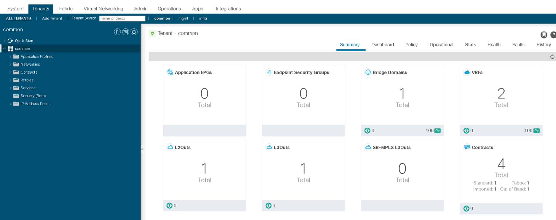
Select the Tenants menu and choose a predefined tenant, common.The work pane displays details about the component that is selected in the Navigation pane.
Expand the Fabric > Inventory > Fabric Membership and examine the switches listed in the Registered Nodes tab. If necessary, scroll to the right to see all information.

Your topology consists of three physical nodes (two leaves and one spine) and no virtual nodes. The node names and node IDs have been assigned to the switches during registration.


LEAVE A COMMENT
Please login here to comment.