EMAIL SUPPORT
dclessons@dclessons.comLOCATION
USACI Topology & Components
Cisco ACI fabric uses a spine-leaf topology. High-bandwidth links between the spine and leaf switches provide transport to an integrated overlay. The host traffic that arrives at the ingress leaf and needs to be sent to an egress leaf is carried over an integrated overlay. All access links from endpoints are attached to the leaf switches, which provide a high port density, while the spine switches (minimum of two spine switches for redundancy) aggregate the fabric bandwidth.
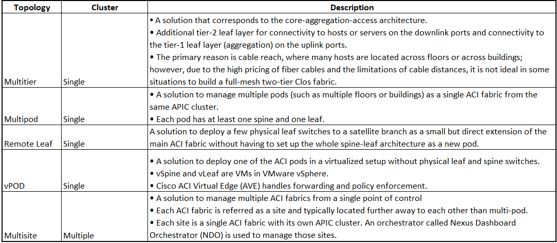
Starting with the Cisco APIC Release 4.1(1), you can now create a multitier Cisco ACI fabric topology that corresponds to the core-aggregation-access architecture. The new design for Cisco ACI incorporates the addition of a tier-2 leaf layer for connectivity to hosts or servers on the downlink ports and connectivity to the leaf layer (aggregation) on the uplink ports.
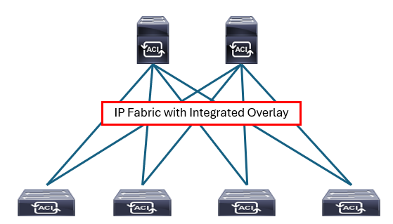
The Cisco ACI fabric is composed of the Cisco APIC and the Cisco Nexus 9000 Series spine and leaf switches. With Cisco ACI, APICs manage the infrastructure IP address space and automatically allocate proper IP addressing required for the leaf and spine. The infrastructure IP addresses are in a separate virtual routing and forwarding (VRF) than the user data traffic so that the infrastructure IP is contained within fabric and won’t have any overlapping IP address issues. The infrastructure VRF is transparent to external traffic. You specify this IP address range, which is called tunnel endpoint (TEP) pool, during the Cisco APIC initial configuration.
The Cisco ACI fabric must be configured with an active Network Time Protocol (NTP) policy to assure that the system clocks on all devices are correct. Atomic counters that are used to detect drops and misrouting in the fabric also require an active fabric NTP policy.
IS-IS Frabric Routing
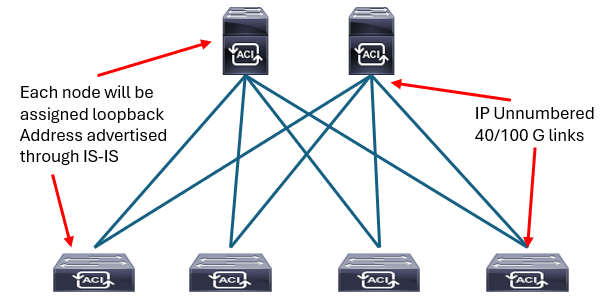
The fabric applies a densely tuned Intermediate System-to-Intermediate System (IS-IS) environment utilizing Level 1 connections within the topology for advertising loopback addresses. Loopback addresses are the Virtual Extensible LAN (VXLAN) Tunnel Endpoints (TEPs) that are used in the integrated overlay and advertised to all other nodes in the fabric for overlay tunnel use.
IS-IS is responsible for infrastructure connectivity in Cisco ACI:
- IS-IS provides IP reachability among TEP addresses
- Automatically deployed, no user intervention is required
- No IS-IS knowledge is required
Endpoint Forwarding Across Leaf Switches
When a packet is sent from one leaf to another, an end host (called an endpoint in ACI) location is identified by a TEP IP of each node. User data traffic is encapsulated with VXLAN header when being forwarded to another leaf. The forwarding across switch nodes is performed based on the TEP IP in the VXLAN encapsulation. In case the ingress leaf is not aware of the destination endpoint location (TEP), ACI has a distributed database called Council of Oracles Protocol (COOP) on each spine that knows all the mapping of endpoint and TEP.
Deployment Options
A single organization may have multiple data centers, each with different requirements and business usage.
For example, a cloud service provider can have its own data center infrastructure for internal operations and another infrastructure for its customers’ cloud services. The data centers may be positioned in a single location, in multiple floors or buildings, or in multiple locations that need to be interconnected.
The following tables list the major deployment types.
Cisco APIC
Cisco APIC is a policy controller. It relays the intended state of the policy to the fabric. The APIC does not represent the control plane and does not sit in the traffic path. The hardware consists of a cluster of three or more servers in a highly redundant array.
Cisco APIC has these roles:
-
It is the policy controller:
-
Holds the defined policy
-
Represents the management plane
-
Not the control plane
-
Not located in the traffic path
-
-
Instantiates the policy changes
-
-
It is deployed as a redundant cluster of servers
The Cisco APIC appliance has two form factors for medium or large configurations. Medium configurations have a medium-size CPU, hard drive, and memory for up to 1000 edge ports. Large configurations have large-size CPU, hard drive, and memory for more than 1000 edge ports.
A Cisco APIC appliance cluster is comprised of either Cisco Unified Computing System (UCS) C220 M5 as third-generation appliances (which are referred as Cisco APIC-M3 or Cisco APIC-L3, intended for medium or large configurations respectively), Cisco UCS C220 M4 as second-generation appliances (Cisco APIC-M2/L2), or Cisco UCS C220 M3 (Cisco APIC-M1/L1) as first-generation appliances.
The Cisco APIC software is delivered on the Cisco UCS server appliances with an SSL certificate that allows the hardware to run Cisco APIC software. The product consists of the server hardware and preinstalled Cisco APIC software. Since the hardware is Cisco UCS C-Series, it comes with Cisco Integrated Management Controller (IMC).
Cisco APIC Redundency
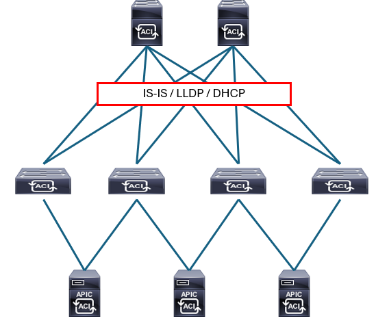
Cisco APICs use a bonded interface that is typically dual-homed to two leaf switches for connectivity to the Cisco ACI fabric, and have the ability to use a bonded interface that can be dual-homed to the out-of-band management network. There are two bond interfaces:
-
Bond0 is used to connect to the fabric itself (to connect to leaf switches that connect into the fabric). It is recommended to connect two fabric uplinks, each to a separate leaf and/or vPC Leaf pairs.
-
Bond1 is used to connect to the out-of-band (OOB) segment (that allows setup of the APIC itself).
The following figure depicts the Cisco APIC M3/L3 server rear panel, indicating the Bond0 on the Cisco UCS VIC 1455 card with 4 external 10/25-Gigabit Ethernet ports and Bond1 on the dual 1-Gb/10-Gb Ethernet ports. To access Cisco Integrated Management Controller (CIMC) the port dedicated to a console (1-Gpc RJ-45 Ethernet) connection should be used.
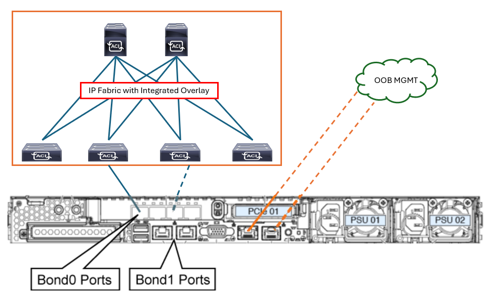
The four ports on the Cisco UCS VIC 1455 are paired in the following manner: port-1 and port-2 (from left to right) represent one pair, corresponding to eth2-1 on APIC and port-3 and port-4 is another pair, corresponding to eth2-2 on APIC. Eth2-1 and eth2-2 form the Bond0, which is an active/standby Port Channel. Only one connection is allowed for each pair. For example, you can connect one cable to either port-1 or port-2, and connect another cable to either port-3 or port-4 (please do not connect two cables on any pair).
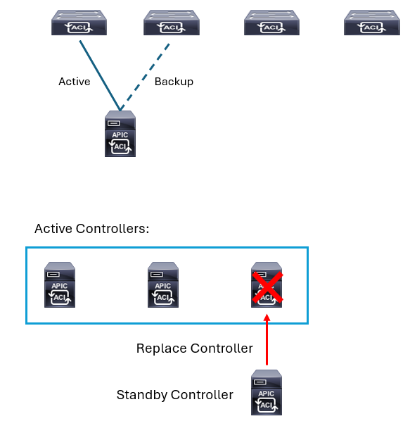
On top of the three (or more) APICs that actively form a cluster, one could have a standby APIC. The standby APIC functionality enables you to operate the APICs in standby mode. In an APIC cluster, designated active APICs share the load, and the designated standby APICs can act as a replacement for any of the APICs in an active cluster.
You can configure the standby role when the Cisco APIC is launched for the first time. You should have at least three active APICs in a cluster, and one or more standby APICs.
The standby APIC is automatically updated with firmware updates to keep the backup APIC at same firmware version as the active cluster. Each Cisco APIC controller, active or standby, has an ID that designates it within the cluster. The ID of a standby controller changes when it switches over to an active APIC. The standby controller takes over the ID of the replaced (previously active) controller, while keeping its formerly configured name.
Cisco APIC Cluster
Cisco APIC is deployed in a cluster with a minimum of three controllers. Any controller in the cluster can service any user for any operation, and a controller can be transparently added to or removed from the cluster. APICs form a cluster and talk to each other using infra network provided by leaf and spine.
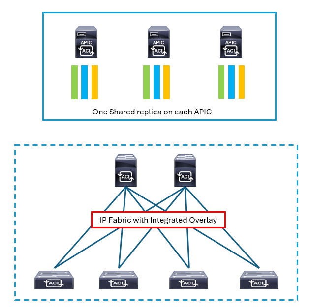
The APIC cluster uses a large database technology called sharding. The APIC configuration database is partitioned into logically bounded subsets, called shards, and each shard has three replicas. The shards are evenly distributed across the APICs. This specific database technology provides scalability and reliability to the data sets that are generated and processed by the Cisco APIC.


LEAVE A COMMENT
Please login here to comment.