EMAIL SUPPORT
dclessons@dclessons.comLOCATION
USVXLAN BGP EVPN Communication with External FW
In this chapter we will learn , how to implement Active/Standby FW Cluster into VXLAN Fabric.
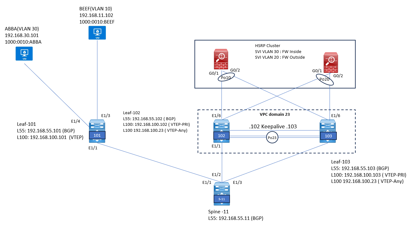
Below will be the Physical topology we will use to understand the Physical Connectivity.
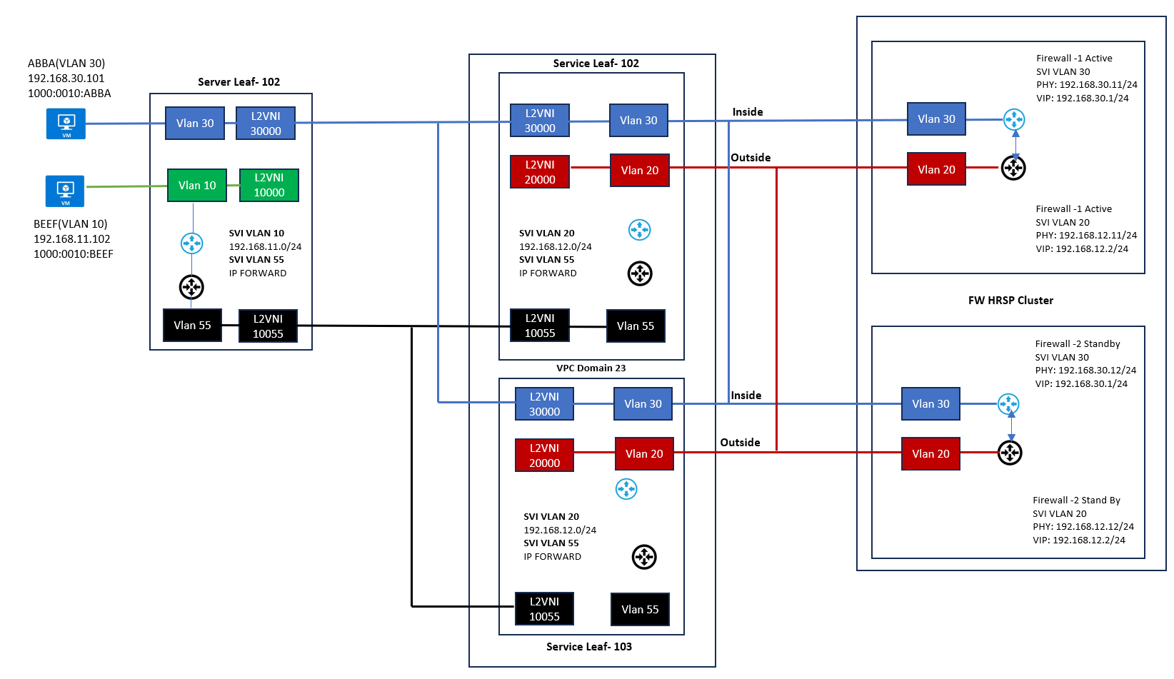
Below figure shows the logical view of example setup, where there are two server networks: 192.168.30.0/24 (VLAN30 - protected) and 192.168.11.0/24 (VLAN10 - non-protected). We also have an Active/Standby FW Cluster connected to dedicated Service Leaf vPC Cluster (Leaf-102 and Leaf-103). Anycast Gateway (AGW) for the network 192.168.11.0/24 resides in the Server Leaf-101 while the Gateway for the protected network 192.168.30.0/24 resides in the Firewall (Inside Zone). Protected hosts in VLAN 30 use the VXLAN Fabric only as an L2 transport network.
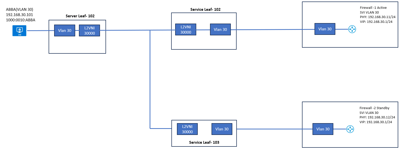
Protected Network Segment
Server Leaf-102, where host Abba is connected to, has a VLAN 30 mapped to L2VNI 30000. BGP EVPN is used as a Control plane protocol to advertise host MAC/IP information. The same configuration is also added to Server Leaf-102 but as we can see in figure 14-2, neither switch has Anycast Gateway configured to VLAN 30. The Default Gateway for VLAN 30 is configured on the FW-1. This is one way to create a protected segment on VXLAN fabric.
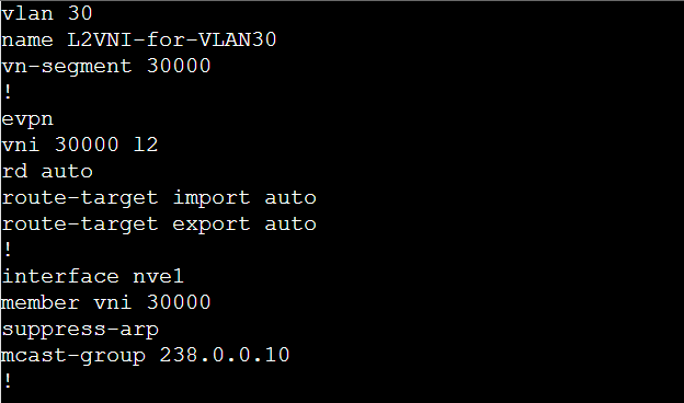
The L2 configuration of Leaf switches form a protected network perspective is shown in example. First, VLAN 30 is mapped to L2VNI 30000 and then added under the EVPN configuration. Under NVE1 interface, the L2VNI specific settings such as ARP suppression and multicast group for BUM traffic are defined
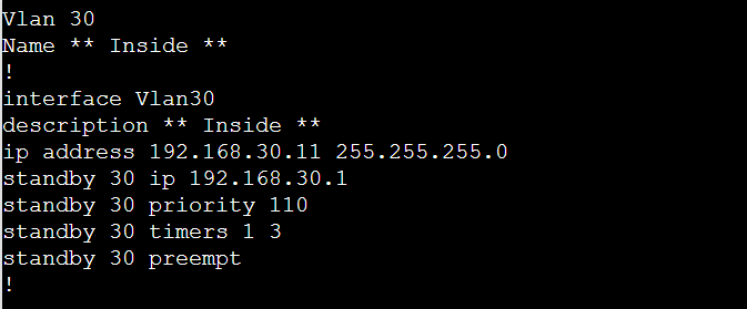
Below is the FW-1 configuration related to VLAN 30.
Non-Protected Network Segment
The configuration for the non-protected segment in Server Leaf-102 . First, VLAN 10 is created and mapped into L2VNI 10000. Anycast Gateway for the network 192.168.11.0/24 is 192.168.11.1. Then L2VNI 10000 is created under the EVPN configuration.


LEAVE A COMMENT
Please login here to comment.