EMAIL SUPPORT
dclessons@dclessons.comLOCATION
USService Graph In Multi-Pod
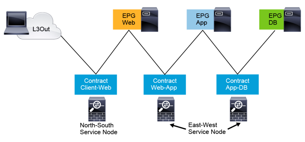
The three most CiscoWorks Common Service node insertion use cases are :
-
North-south perimeter firewall: Traffic flows between the external Layer 3 network domain and the web EPG.
-
East-west firewall (intra-VRF): Traffic flows from the web EPG to the application EPG and from the application EPG to the database EPG.

-
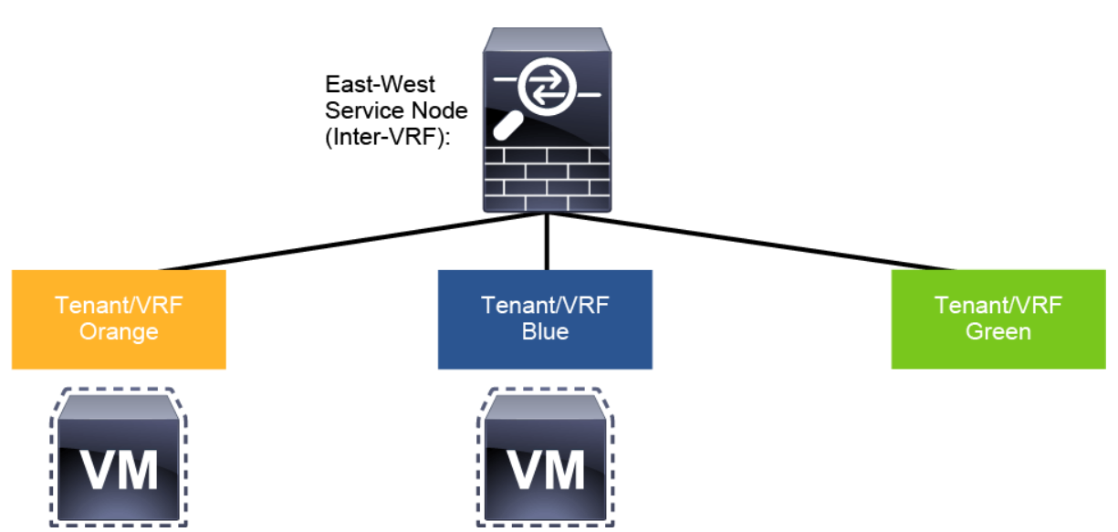
East-west firewall (inter-VRF): Traffic flows between EPGs that are part of different VRFs when the firewall is front-ending each VRF.

Service graph option in Cisco ACI Multi-Pod fabric can help you integrate service nodes in the following commonly used high-availability models:
-
Active-standby service node pair stretched across pods
-
Transparent firewall: The inserted service node bridges two bridge domains. The external network traffic (north-south) or between internal endpoints (east-west) is processed by the active service node pod, which operates in transparent mode.
-
Routed firewall as default gateway for the endpoints: Cisco ACI fabric offers Layer 2 connectivity services to allow the endpoints to communicate with their default gateway (the firewall) and for the firewall to route traffic between endpoints belonging to separate IP subnets and between the endpoints and the external Layer 3 network domain.
-
Routed firewall with L3Out peering: Integrates a north-south routed firewall when the firewall nodes are connected to the Cisco ACI fabric via L3Out peering, or provides east-west routed firewall insertion with L3Out peering, where the routed path between the web EPG and app EPG always goes through the active firewall, no matter in which pod it is deployed.
-
Routed firewall with PBR: Facilitates north-south routed firewall or east-west routed firewall insertion with PBR.
-
-
Active-active service node cluster stretched across pods
-
Routed firewall with PBR: Uses Cisco ACI fabric for Layer 2 and Layer 3 forwarding and only redirects traffic of interest (as defined in PBR) toward the anycast service. Depending on the type of traffic, the service graph with PBR can be used in:
-
North-south use case, where the endpoints that are connected to the Cisco ACI fabric use the fabric itself as the default gateway. Traffic that is destined to those endpoints and originating from the external Layer 3 domain (or vice versa) is redirected to the firewall cluster with the configured PBR policy.
-
East-west use case, where communication can be achieved between EPGs that are part of the same VRF or part of different VRFs. For the intra-VRF communication, the PBR policy is usually applied on the inbound leaf where the endpoint sourcing the traffic is connected, while for the inter-VRF scenario, the PBR policy is instead always applied on the consumer VRF.
-
-
-
Independent active-standby service node pair that is connected to separate pods
-
Routed firewall with L3Out peering: It is critical to ensure that inbound traffic is always delivered to the “right pod,” meaning to the pod where the destination endpoint is connected, which can be achieved by using more granular host route advertisement into the WAN. This option is suitable for north-south perimeter service node integration.
-
Routed firewall with symmetric PBR: The Cisco ACI PBR can associate multiple instances of service nodes with the same PBR policy and can load-balance different traffic flows across those nodes. Ingress and egress traffic flows can then be redirected to the same PBR node, using the symmetric PBR function. Similarly, this option can be utilized for north-south routed firewall and east-west routed firewall insertion.
-
Active-Standby Firewalls Stretched Across Pods
All traffic for communication with the external network (north-south) or between internal endpoints (east-west) must be hair-pinned to the pod in which the active service node is located.
Multi-Pod Flow Consideration Scenario 1: Transparent Firewall
You can implement active-standby transparent firewalls pair that is stretched across pods for the north-south or east-west traffic protection.
The following figure depicts the typical Cisco ACI network design for insertion of a north-south transparent firewall, which you can use for all service graph models, and without a service graph.
 The default gateway for the web server part of the Web EPG is deployed in the Cisco ACI fabric and is available in the bridge domain (BD1) in which the firewall external interface is connected. This bridge domain (BD1) is different from the one (BD2) in which the web server is located.
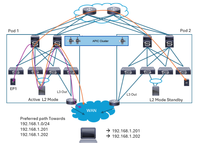
When you use traditional L3Out for external network connectivity, you need to pay attention at which pod may receive the packet from L3Out since the packet may be received on a pod that does not have active firewall. As mentioned in “Connectivity to External Layer 3 Networks” topic, Host Route Advertisement feature should be used in such scenario. The following figure shows Host Route Advertisement feature advertise host routes for endpoint IP on top of BD subnet so that traffic can be received on the pod with active firewall. This prevents packets to go back and forth inefficiently between pods.

Multi-Pod Flow Consideration Scenario 2: Routed Firewall with L3Out Peering with the ACI
You can implement routed firewalls that are stretched across pods with L3Out peering for the north-south or east-west traffic protection.


LEAVE A COMMENT
Please login here to comment.