EMAIL SUPPORT
dclessons@dclessons.comLOCATION
USService Appliance Insertion Without ACI L4-L7 Service Graph
Cisco ACI technology provides the capability to insert Layer 4 through Layer 7 functions using an approach called a service graph (described below). In Cisco ACI, you also can insert service devices such as load balancers in the path without a service graph. To do so, you need to treat them as External Layer 2 Connectivity (EPG Extension) or External Layer 3 Connectivity (L3Out).
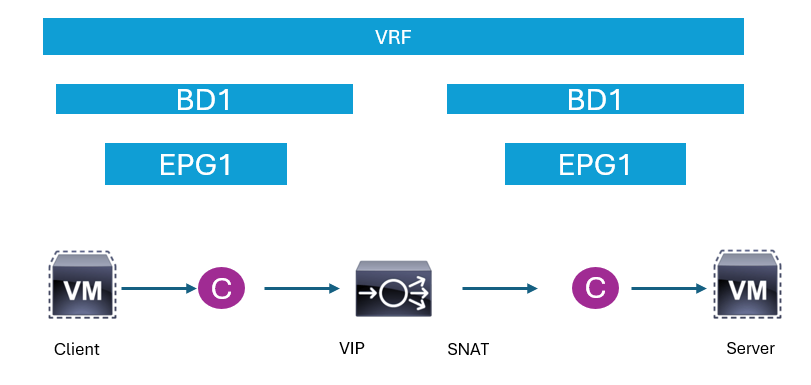
The figure below shows an example logical topology where the client VM reaches to the VIP of the load balancer, and the load balance will perform source NAT (SNAT) to hide the client IP address from back-end servers prior to forward packets to them. Contracts here are used to allow only a specific type of traffic to reach to the load balancer, and eventually the back-end server.

Service Appliance Insertion via ACI L4-L7 Service Graph
With the ACI L4-L7 Service Graph, some of the configurations can be automated. The biggest benefit of Service Graph is to allow users to focus on contracts between client VM and back-end servers instead of worrying about contracts between client VM and a load balancer, a load balancer, and back-end servers in the previous example. Although it simplifies and automates the contract security part of the configuration, users still need to carefully design the network topology to ensure that traffic will flow through a service node such as a load balancer. In case the traffic flow needs to be bent towards a service node against a routing table or endpoint table, the Service Graph Policy Based Redirection (PBR) feature needs to be used.


LEAVE A COMMENT
Please login here to comment.