EMAIL SUPPORT
dclessons@dclessons.comLOCATION
USWhat is Undelay in VXLAN
Underlay network is used to provide the IP connectivity between VXLAN Tunnel End Point (VTEP) devices. This underlay network is also used for BUM traffic known as Broadcast, Unknown unicast, Multicast traffic. In VXLAN most common underlay protocol used is either OSPF and IS-IS or we also use BGP as underlay.
OSPF Operation
In this chapter we will learn, How the Dijkstra/Shortest path First ( SPF) algorithm work in OSPF , in order to calculate Shortest-Path Tree. We will see how this SPT calculation process cab be optimized by disabling or finetuning the advertisement of unnecessary LSU information.
We know that OSPF exchanges LSU packets with adjacent routers. These LSU contains multiple LSA , in which router describes its links. Once the LSU are received, and after successful validation , Router stores the link state information in to its Database called as LSDB and floods it to adjacent routers.
Once the LSDB is synchronized, routers runs the Dijkstra algo to find the shortest path to each destination.
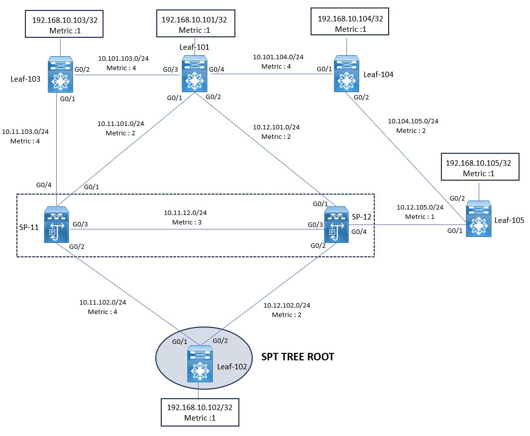
Below topology is used to understand out SPT is created in OSPF. This topology is standard Spine-Leaf topology , where Leaf-101,102,103,104,105 are connected on Spine-11 and spine-12 , as shown in figure.
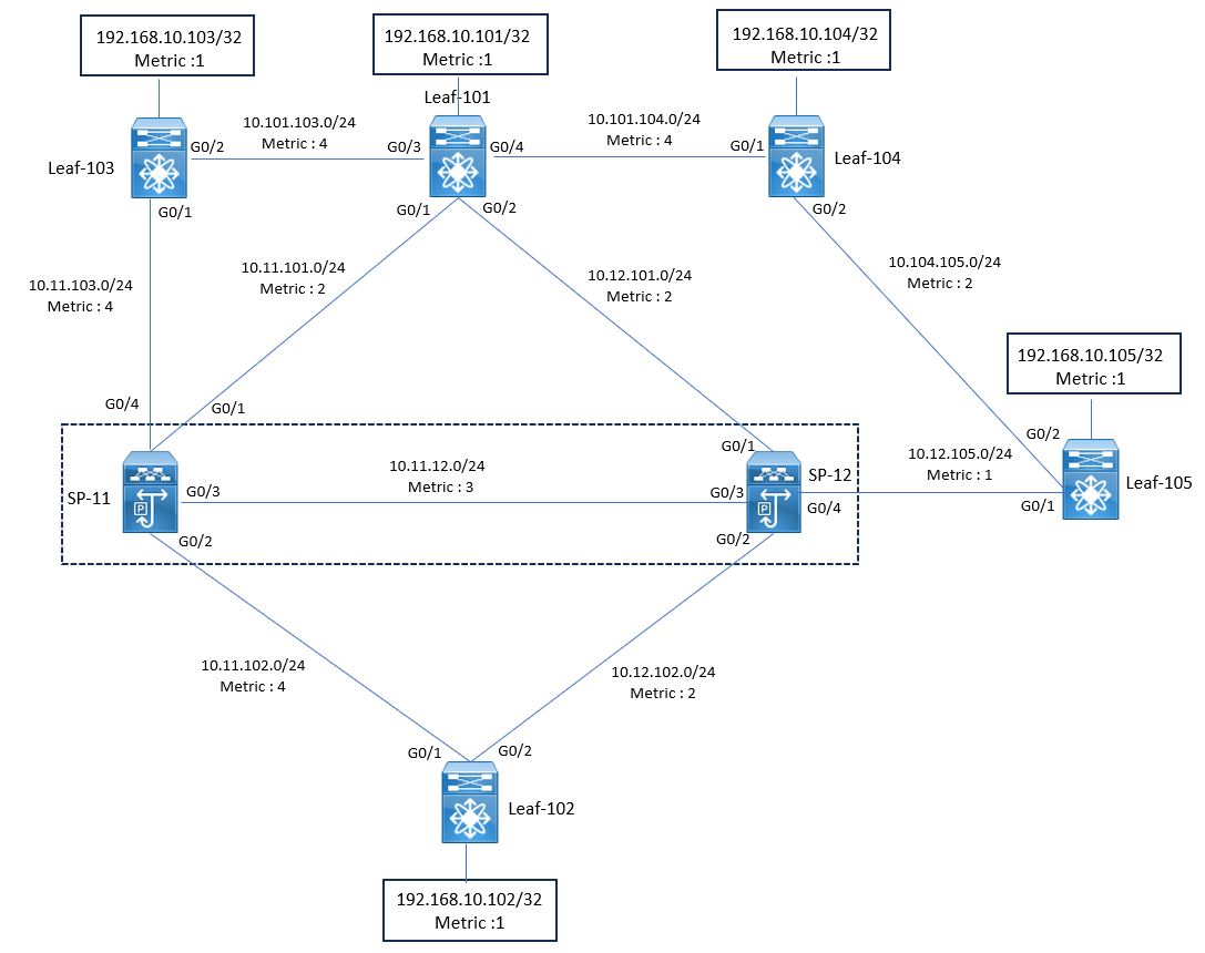
All Inter switch link and loopback address are under OSPF area 0.0.0.0. Each connected link has metric value , which are statically configured on per Interface.
Router ID is statically configured based on nomenclature: 192.168.0..
Link-State Database (LSDB) Optimization
We know that , if Routers are connected over Ethernet link , the default OSPF network type will be Broadcast . In this scenario , for each Link Segment , One DR and One BDR will be elected among themselves.
All Non-Designated routers will send the Router LSA only to DR and DR will in turn floods the Network LSA to other router in same segment.
In Below figure LSA will be generated from Leaf-102 , which is DR for each segment connected to Spine-11 and Spine-12. Leaf-102 originates the LSU packet , which carries both Router LSA and Network LSA and send it to both adjacent Switches.
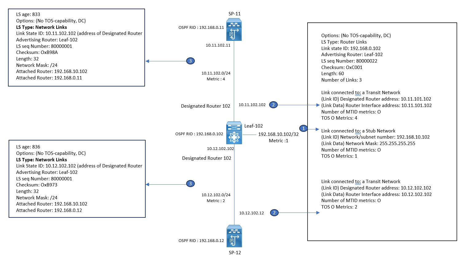
Here , as we have only two routers in each segment , so election of DR and BDR is useless. So in order to optimize the LSDB , change the OSPF network type from Broadcast to Point-to-Point and this adjacent router will exchange only Router LSA’s.
Now once this change is done , lets examine by looking in to below figure , where Router LSA is generated by leaf-102. Leaf-102 describes its neighbor routers and the local interfaces by using Link Type-1 Router LSA ( shown as Link connected to another router). This interface information is used for Routing.
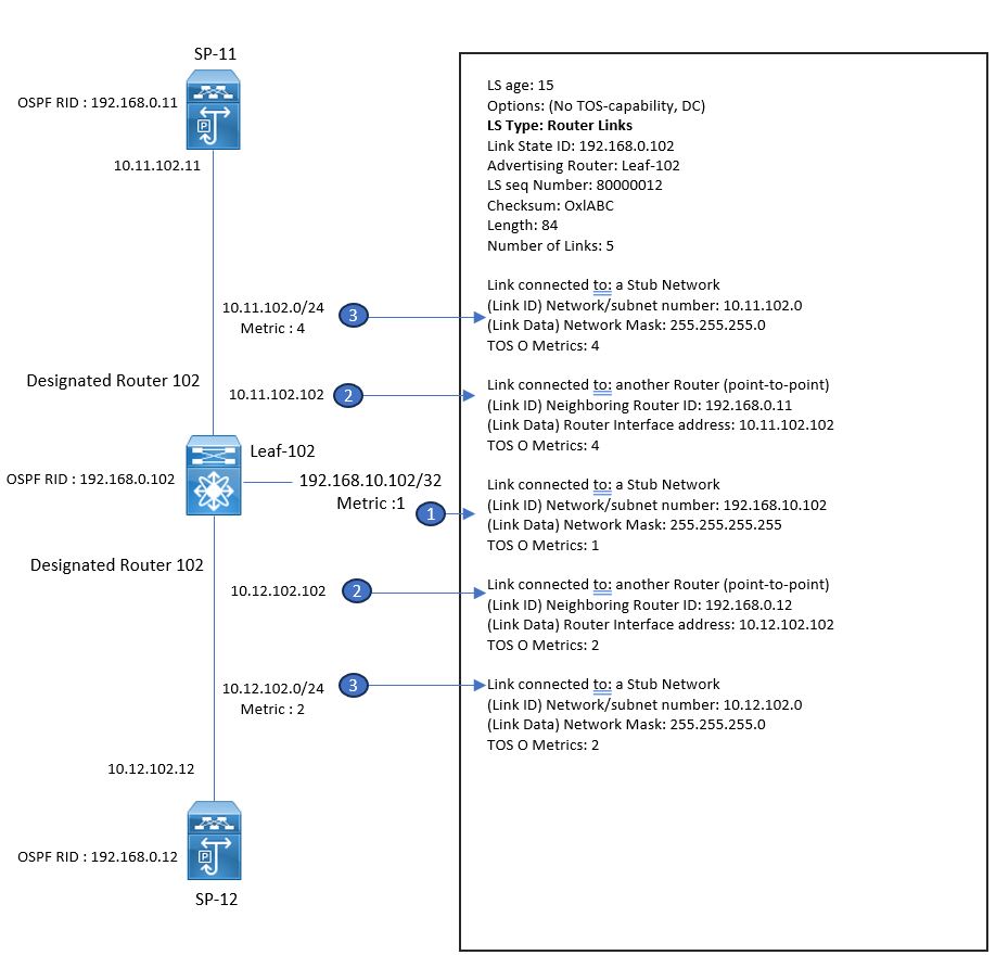
Also Leaf-102 describes the subnet to which the routers are connected to by using Link Type 3 Router LSA ( “connected to Stub Network “)
The sub-network are also called as transit network , are not used for data traffic and thus consume unnecessary hardware resources and decreases convergence time. So these unnecessary transit network LSA can be suppressed by using Prefix Suppression.
Below figure shows LSDB taken from leaf-102 before prefix suppression , where Link count in Area 0 is 45.

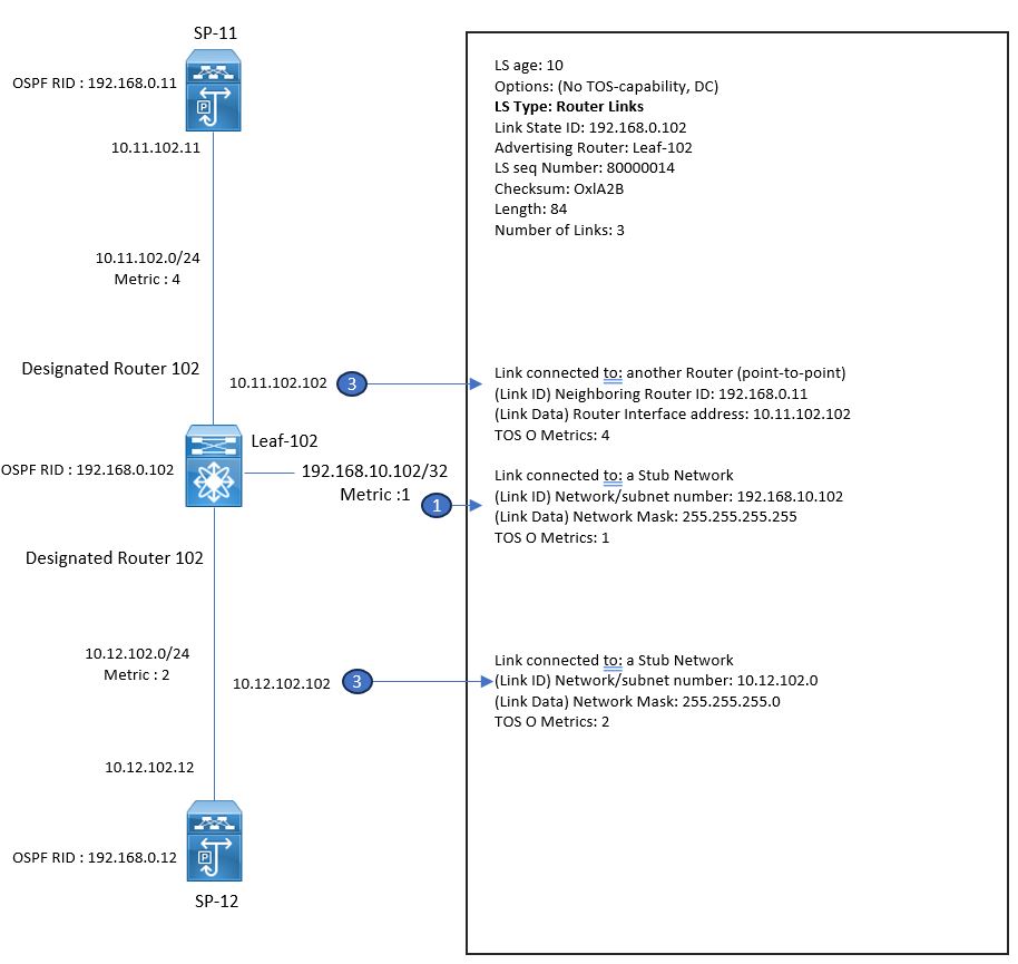
Now as soon as you change the OSPF network type from Broadcast to Point-to-point , using prefix-suppression option , the count is reduced from 45 to 25.
Below figure explains the OSPF LSDB from Leaf-102 after Prefix suppression.
Leaf-102(config)# interface g0/1
Leaf-102(config-if)# ip ospf network point-to-point
Leaf-102(config-if)# ip ospf prefix-suppression

Shortest-Path First (Dijkstra Algorithm)
This Algo is used to calculate the shortest path tree topology in OSPF Area. In this Also , Each router itself select itself as ROOT of the tree and then forms the SPT using the Type-1 link description in Router LSA. When SPT is formed, router calculates the distance to subnets connected to each router by using Link Type-3 (Stub) description in Router LSA.
In STP, Each router forms two list , one is called as candidate list : which includes all routers that are currently examined by the router.
Another List is called as Tree List: also called as path List, which includes all routers participating in a final SPT.
Dijkstra Algo runs in two phase:
- Phase 1: Building a Shortest path Tree.
- Phase 2: Adding Leaf’s to SPT.
Lets discuss these phases one by one.
Phase 1: SPF RUN : Building a Shortest-path tree
In this phase Leaf-102 starts the Shortest-path tree calculation , where Leaf-102 inserts itself in to the candidate-list with cost 0 with next hop pointing towards Itself. Where as all other leaf switches are in Unknown-list in this phase.
Refer below figure to understand the SPT calculation: which is a starting point of this.

First Iteration Round:
Now in this step , Leaf-102 inserts itself to path list and examines its own self originated Router LSA.
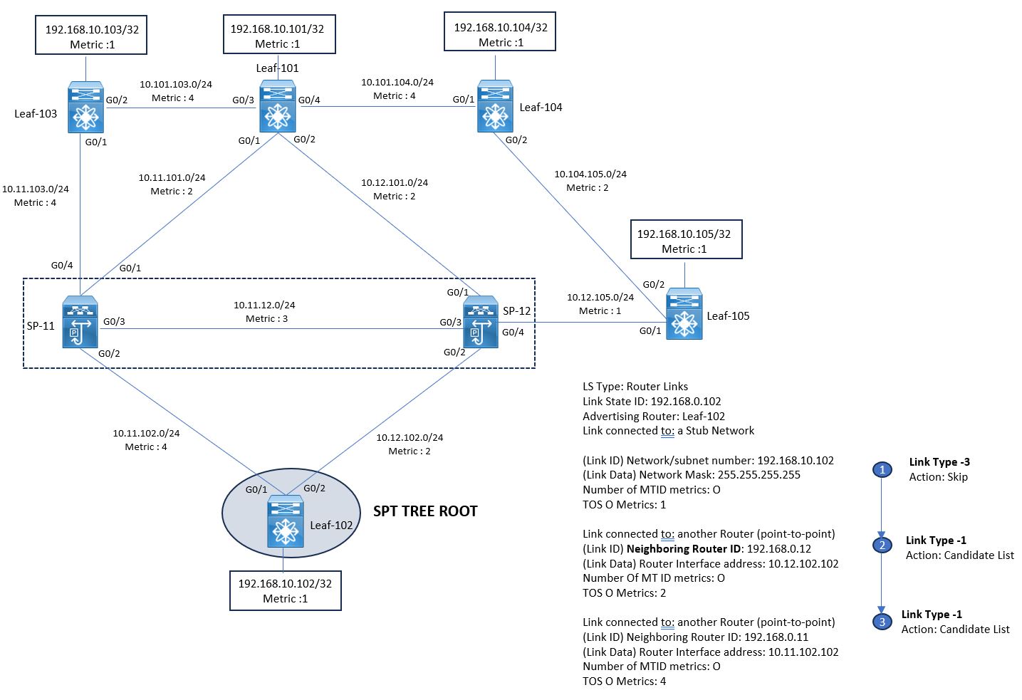
Where it puts the Spine-12 with cost 2 and Spine-11 with cost 4 in its candidate list , because it is Link Type-1, and ignores the First LD that is Link Type 3 ( Stub ).
Leaf-103, Leaf-104 , Leaf-105 are still in the Unknown list.

Second Iteration Round :
In this round , Leaf-102 moves Spine-12 to the path list from candidate list , because it has lowest cost among all routers listed in candidate list and starts checking the LSA advertised by Spine-12
Refer below figure to see , what LD will be added in to Candidate list and what will be skipped or not added.
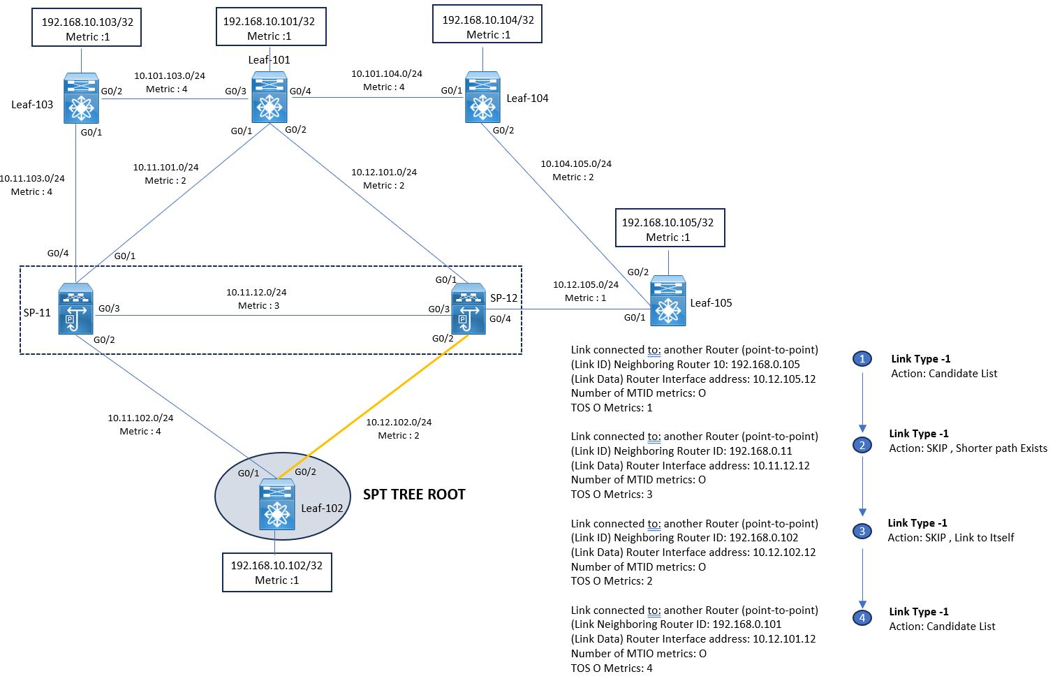
Here Leaf-105 , Leaf-101 is added to candidate list and Link to Spine-11 and link to Leaf-102 is not added to candidate list.

Third Iteration Round
In this Round , Leaf-102 moves Leaf-105 from candidate list to path list , as it has lowest cost among all Candidate list devices. Now Leaf-102 will start checking the LSA advertised by Leaf-105.
Refer below figure to see , what LD will be added in to Candidate list and what will be skipped or not added.
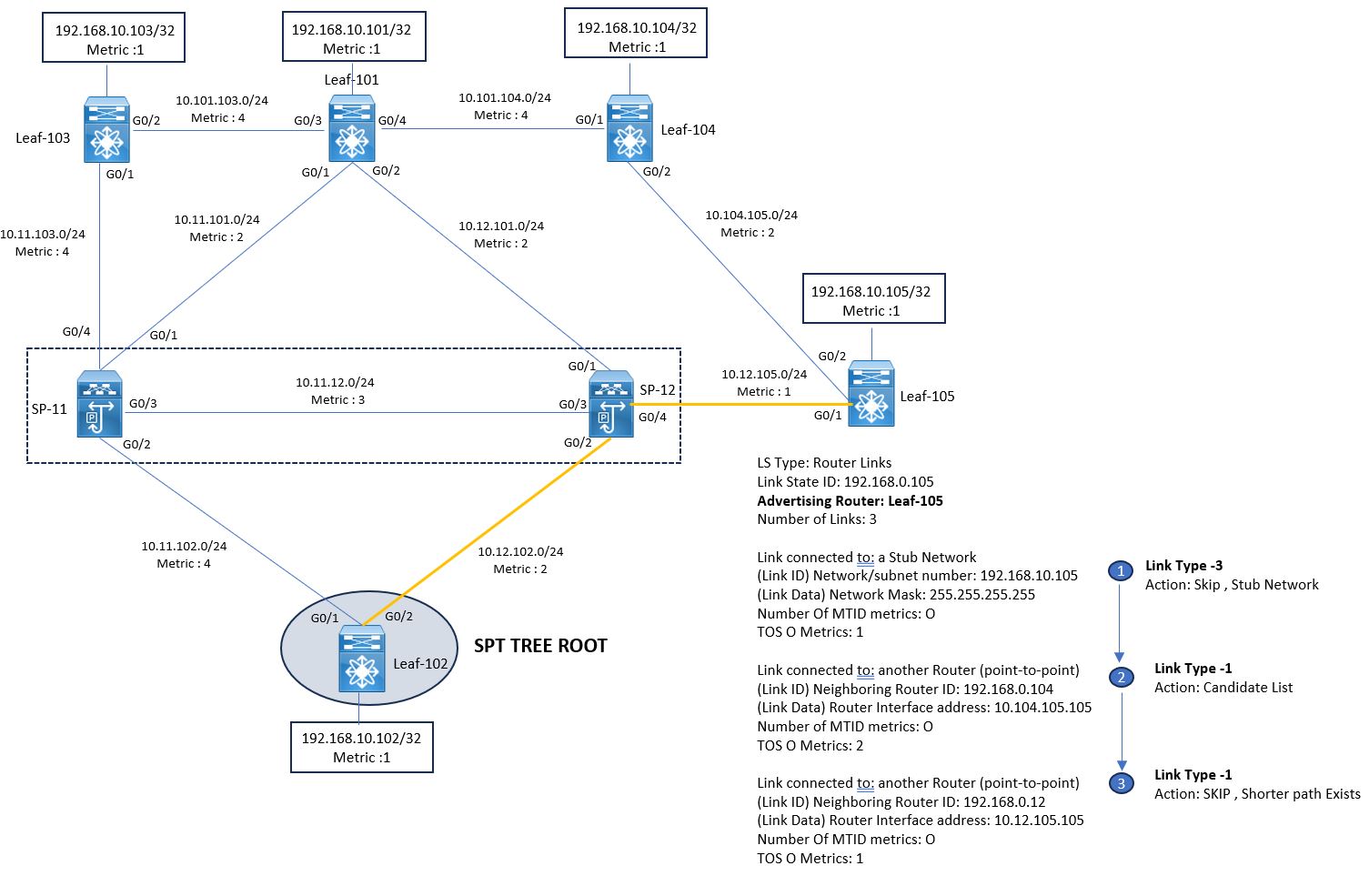
Here Leaf-104 will be added to candidate list and rest all other LD will not be added , description provided in above figure.


LEAVE A COMMENT
Please login here to comment.