EMAIL SUPPORT
dclessons@dclessons.comLOCATION
USMulti-Pod Provisioning & Traffic Flow
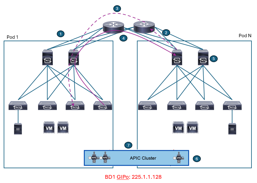
The Cisco ACI Multi-Pod fabric applies different control and data plane functionalities for connecting endpoints deployed across different pods. Once, the Cisco ACI Multi-Pod is successfully provisioned, the information about all the endpoints stored in COOP database in each spine will be exchanged via BGP EVPN through IPN. External route information from L3Outs is exchanged via BGP VPNv4/v6. These are the control plane between pods. Once the forwarding information such as endpoint and L3Out routes are exchanged via control plane, data plane traffic will be forwarded across pods through IPN with TEP and VXLAN encapsulation like within a single pod. Not only unicast traffic, but also flooding traffic can be forwarded seamlessly.
Cisco ACI Multi-Pod Provisioning
Cisco ACI Multi-Pod deployment is automated in a lot of ways to offer easy provisioning with less user intervention.
Initially, the first pod (also known as ‘seed’ pod) should be already set up using the traditional ACI fabric bring-up procedure, and the ‘seed’ pod and the second pod should be physically connected to the IPN devices. Before Cisco ACI Multi-Pod provisioning process can start, you should set up the Cisco APIC and the IPN using the following these steps:
-
Configure access policies: Configure access policies for all the interfaces on the spine switches used to connect to the IPN. Define these policies as spine access policies. Use these policies to associate an Attached Entity Profile (AEP) for a Layer 3 domain that uses VLAN 4 (as a requirement) for the encapsulation for the subinterface. Define these subinterfaces in the same way as normal leaf access ports. The subinterfaces are used by the infrastructure L3Out interface that you define.
-
Define the Multi-Pod environment: For the Cisco ACI Multi-Pod setup, you should define the TEP address for the spine switches facing each other across the IPN. This IP address is used as anycast shared address across all spine switches in a pod. You should also define the Layer 3 interfaces between the spine interfaces and the IPN.
-
Configure the IPN. Configure the IPN devices with IP addresses on the interfaces facing the spine switches, and enable the OSPF routing protocol, MTU support, DHCP-relay, and PIM Bidir. The IPN devices create OSPF adjacencies with the spine switches and exchange the routes of the underlying IS-IS network part of VRF overlay-1. The configuration of the IPN defines the DHCP relay, which is critical for learning adjacencies because the DHCP frames forwarded across the IPN will reach the primary APIC in the first pod to get a DHCP address assignment from the TEP pool. Without DHCP relay in the IPN, zero-touch provisioning will not occur for Cisco ACI nodes deployed in the second pod.
-
Establish the interface access policies for the second pod: If you do not establish the access policies for the second pod, then the second pod cannot complete the process of joining the fabric. You can add the device to the fabric, but it does not complete the discovery process. Thus, the spine switch in the second pod has no way to talk to the original pod, since the OSPF adjacency cannot be established due to VLAN 4 requirement, and the OSPF interface profile and the external Layer 3 definition do not exist. You can reuse the access policies of the first pod as long as the spine interfaces you are using on both pods are the same. Hence, if the spine interfaces in both pods are the same and the ports in all the switches also are the same, then the only action you need to take is to add the spine switches to the switch profile that you define.
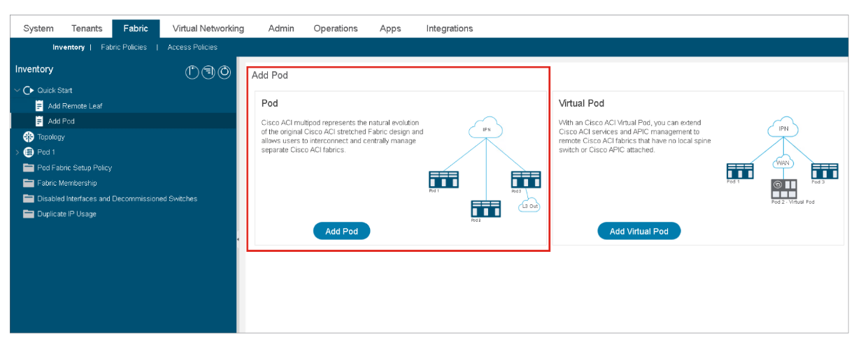
In the Cisco APIC user interface, you can use a wizard to add a pod to the Multi-Pod deployments, which helps you provision the necessary L3Outs on the spine switches connected to the IPN, MTU on all spine-to-IPN interfaces, OSPF configuration towards the IPN, Anycast TEP IP address, and so on. You can invoke this wizard using Fabric > Inventory > Quick Start > Add Pod and choose Add Pod from the work plane, as shown in this figure:
 The Cisco ACI Multi-Pod discovery process follows this sequence:

-
Cisco APIC node 1 pushes the infra L3Out policies to the spine switches in Pod 1. The spine L3Out policy provisions the IPN-connected interfaces on spine switches with OSPF.
At this point, IPN has learned Pod 1 TEP prefixes via spine OSPF. And Pod 1 spine switches has learned IP prefixes on IPN facing to new spines in Pod 2.
-
The first spine in Pod 2 boots up and sends DHCPDISCOVER to every connected interface, including the ones toward the IPN devices.
-
The IPN device receiving the DHCPDISCOVER has been configured to relay that message to the Cisco APIC nodes in Pod 1. It can be accomplished because the IPN devices learned the Pod 1 TEP prefixes via OSPF with spines.
-
-
Subinterface IP of the new spine facing towards IPN.
-
A static route to the Cisco APIC that sent DHCPOFFER, which points to the IPN IP address that relayed the DHCP messages.
-
Bootstrap location for the infra L3Out configuration of the new spine.
The Cisco APIC sends DHCPOFFER, which includes the following initial parameters:
The new spine downloads a bootstrap for the infra L3Out configuration from APIC and configures OSPF and BGP towards IPN. It also sets itself as DHCP relay device for the new switch nodes in the new pod so that DHCP discovery from them can be relayed to APIC nodes in Pod 1 as well.
-
-
All other nodes in Pod 2 come up in a same way as a single pod. Only the difference is the DHCP discovery is relayed through IPN.
-
The Cisco APIC controller in Pod 2 is discovered as usual.
-
The Cisco APIC controller in Pod 2 joins the APIC cluster.
Inter-Pods MP-BGP Control Plane
The COOP database information in each pod is shared via MP-BGP EVPN through IPN so that each pod knows which endpoint is learned in which pod. MP-BGP EVPN runs directly between spine switches in each pod. IPN devices will not participate in this BGP session, but it just provides TEP reachability to establish BGP sessions between each spine switch.


LEAVE A COMMENT
Please login here to comment.