EMAIL SUPPORT
dclessons@dclessons.comLOCATION
USConfigure External Layer 3 (L3Out) Connection
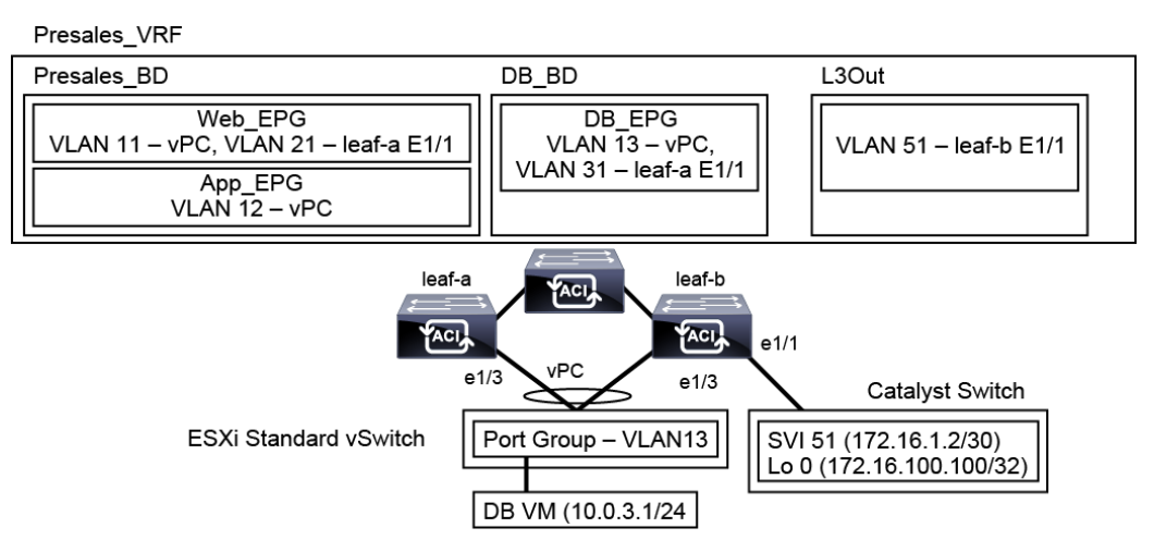
Topology:
 Task:
Task:
In this activity you will deploy OSPF routing between leaf-b and the adjacent Cisco Catalyst switch, and enable communication of the DB_EPG with the external OSPF network, as shown above.
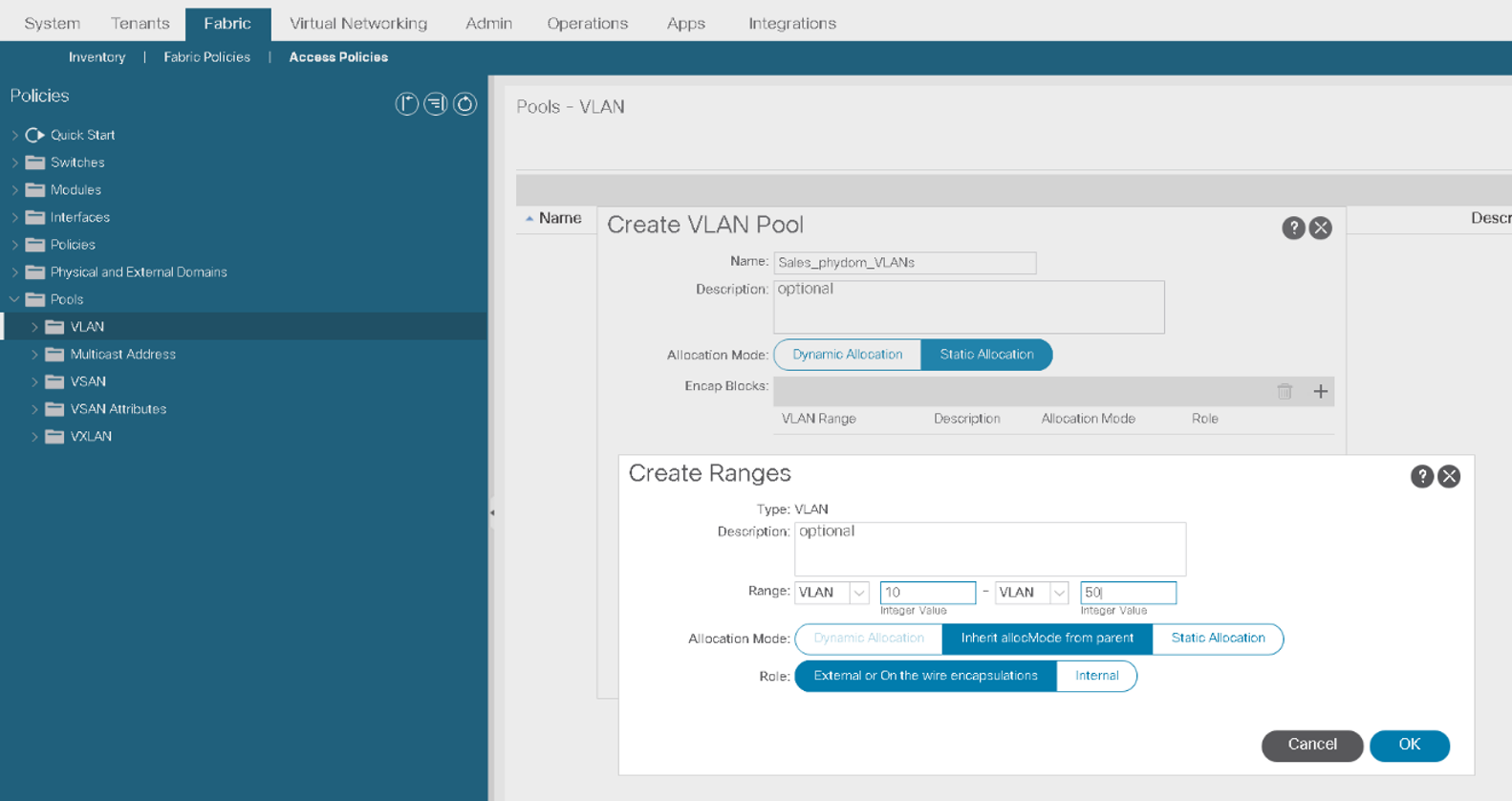
Go to Fabric > Access Policies > Pools > VLAN and create a VLAN pool with the settings below. Click OK and Submit.
-
Name: ExtL3_VLANs
-
Allocation mode: Static Allocation
-
Click + in the Encap Blocks table and configure the range 51–60 with the default allocation mode (Inherit allocMode from the parent) and role (External or On the wire encapsulations).

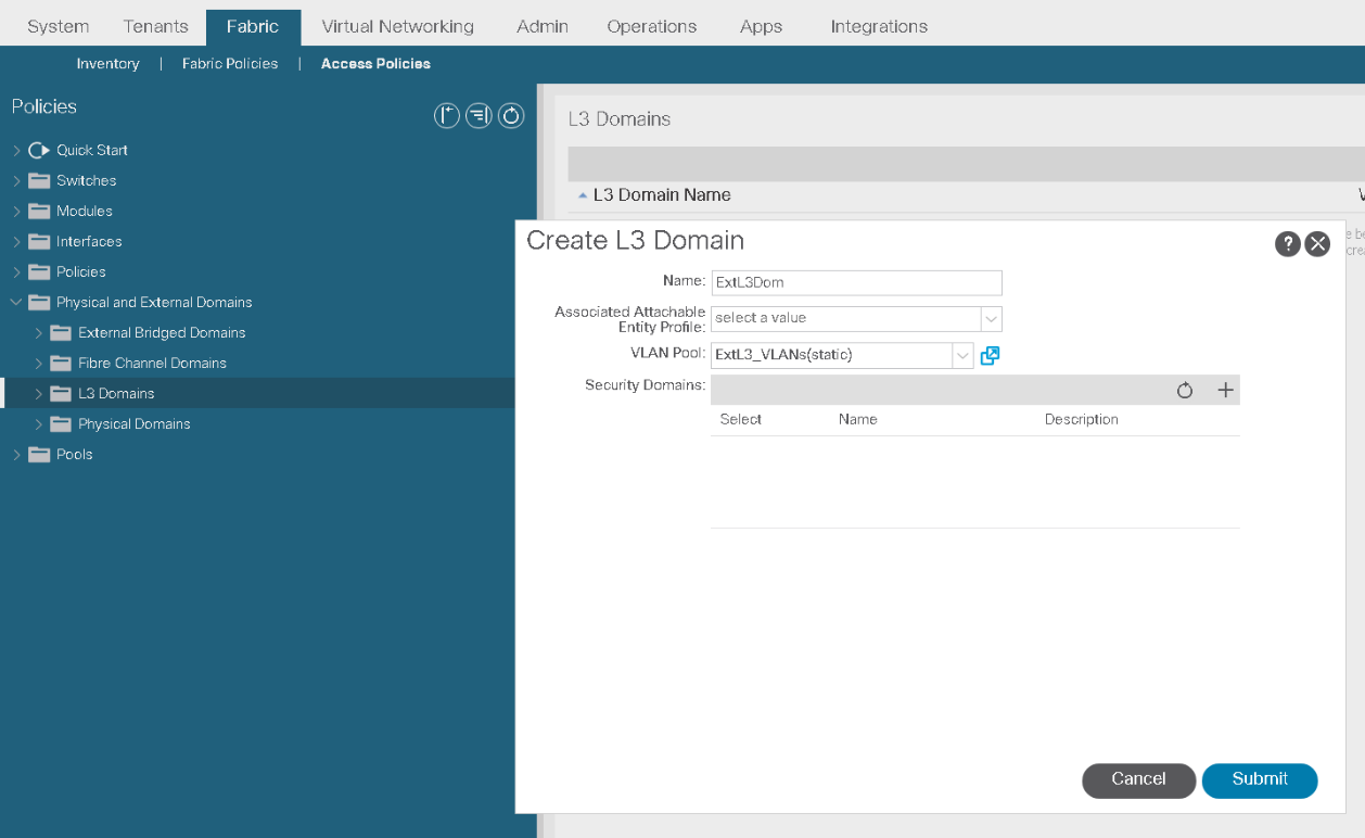
Go to Fabric > Access Policies > Physical and External Domains > L3 Domains, right-click the menu and choose Create Layer 3 Domain.
Create the domain ExtL3Dom that references the VLAN pool ExtL3_VLANs and click Submit.
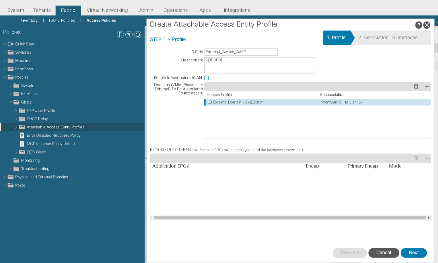
Go to Fabric > Access Policies > Policies > Global > Attachable Access Entity Profiles and create the AAEP EXTERNAL_SWITCH_AAEP. Click +, add the domain ExtL3Dom and click Update. Verify the encapsulation range and click Next.
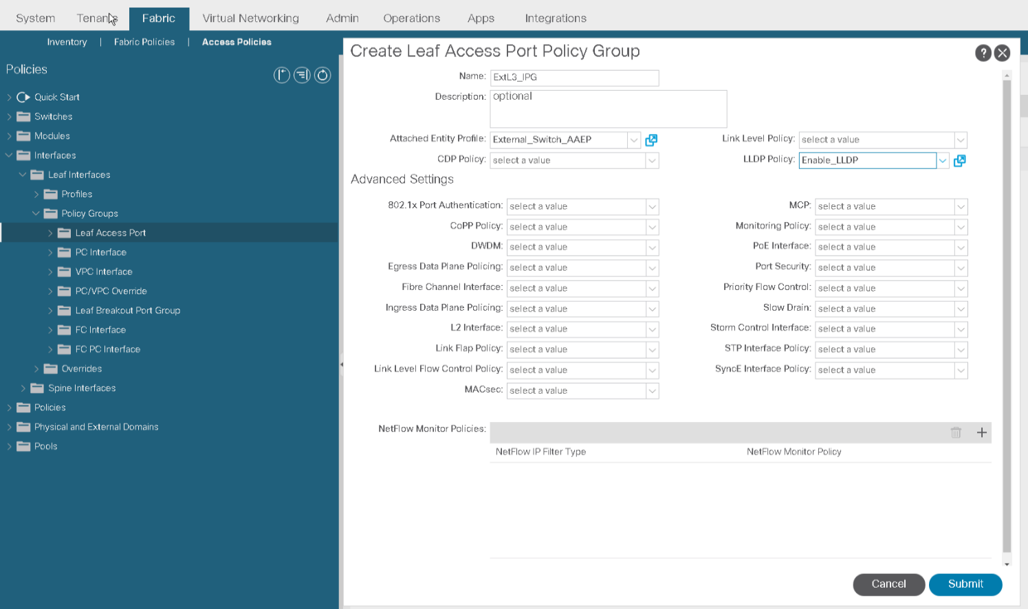
Go to Fabric > Access Policies > Interfaces > Leaf Interfaces > Policy Groups > Leaf Access Port. Create an interface policy group ExtL3_IPG, associate it with EXTERNAL_SWITCH_AAEP and the Link Layer Discovery Protocol (LLDP) policy Enable_LLDP. Click Submit.
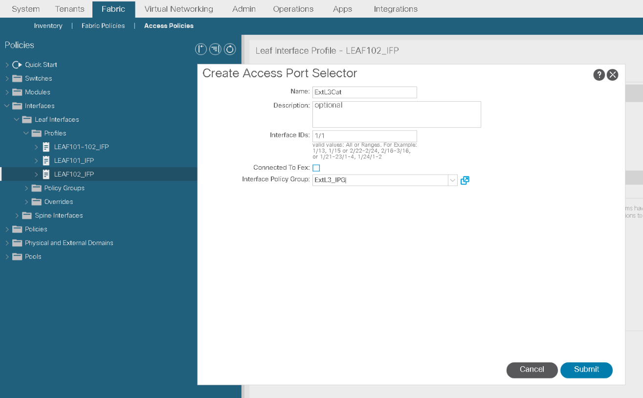
Go to Fabric > Access Policies > Interfaces > Leaf Interfaces > Profiles, expand LEAF102_IFP, click + to configure an interface selector and Continue in the Policy Usage Warning. Configure an interface selector ExtL3Cat for the interface ID 1/1 and associate it with the interface policy group ExtL3_IPG. Click Submit.
Configure L3Out
The OSPF adjacency will be established through the configuration of a L3Out. Use PuTTY to connect to the Catalyst switch (cat). Use appropriate commands to check the OSPF setup.
Go to Tenants >Sales>Networking > L3Outs, right-click the menu, and choose Create L3Out.
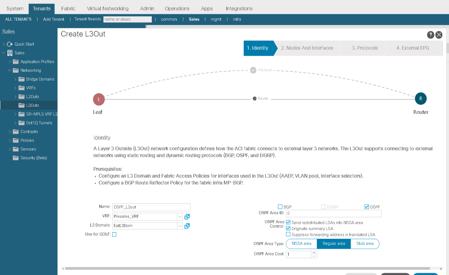
Start creating a L3Out with the settings below. Click Next.
-
Name: OSPF_L3Out
-
VRF: Presales_VRF
-
Layer 3 Domain: ExtL3Dom
-
Routing protocol: OSPF
-
OSPF Area ID: 0 (backbone)
-
OSPF Area Type: Regular area
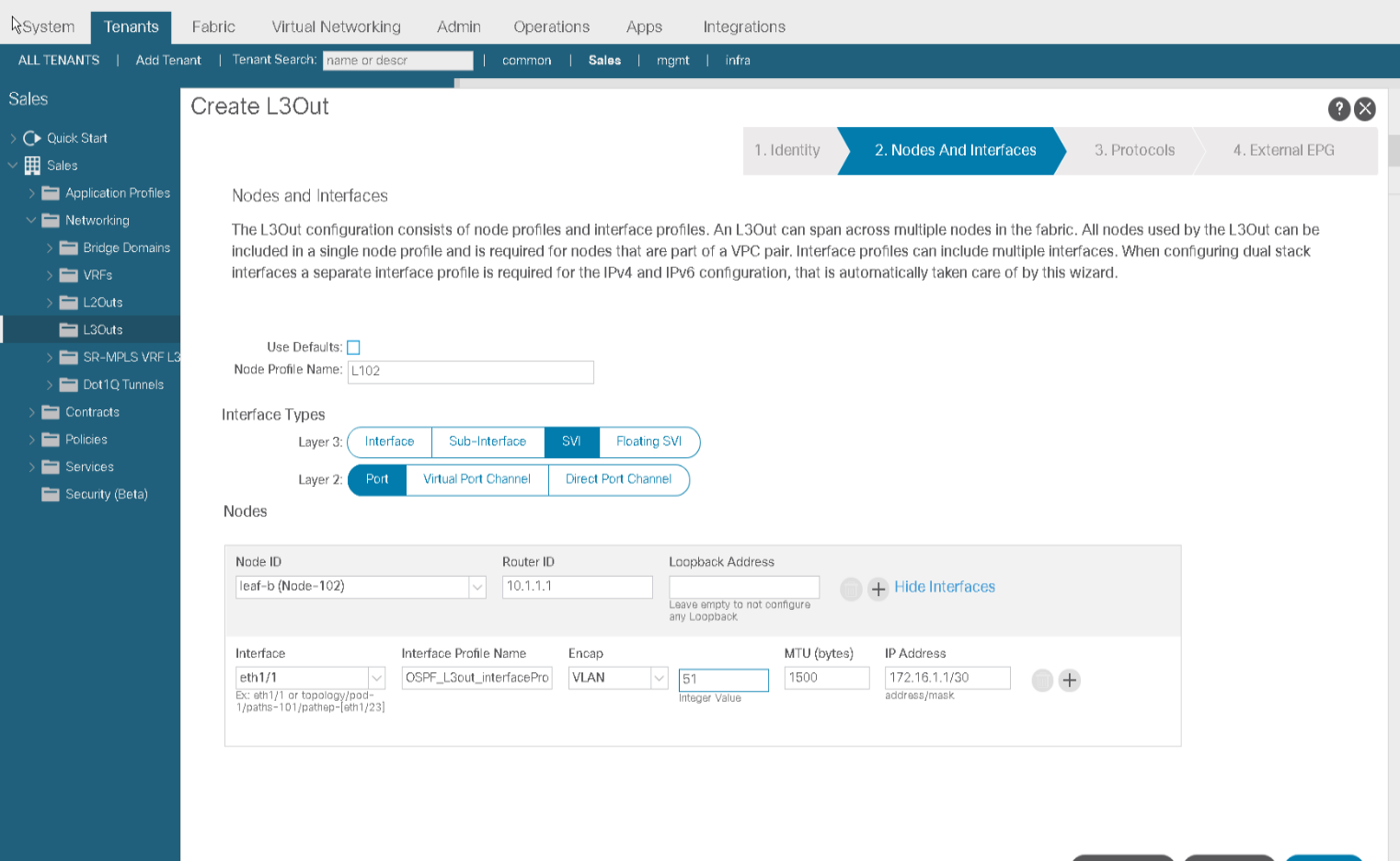
Enter these settings in the Nodes and Interfaces page and then click Next.
-
Clear the Use Defaults checkbox. This will allow you to enter a custom node profile name.
-
Node Profile Name: L102
-
Layer 3:SVI.Recall the interface types for external Layer 3 connections: routed interfaces, routed subinterfaces, switched virtual interfaces (SVIs), and floating SVIs. You will implement the SVIs, which allow multiple connections over a single physical link.
-
Layer 2: Port
-
Node ID: leaf-b (Node-102)
-
Router ID: 10.1.1.1
-
Delete the Loopback Address. You do not need to configure a loopback on the border leaf. Only the router ID is mandatory. In case of BGP, if the BGP peering needs to be sourced from a loopback, you may use this option.
-
Interface: eth1/1
-
Interface Profile Name: OSPF_L3Out_interfaceProfile. The interface profile is a container for interface settings. You can keep the default name.
-
Encap: VLAN
-
VLAN ID:51. 802.1Q tagging supports multiple logical connections over the physical link. The subinterface with the tag 51 is used for L3Out connectivity. This VLAN ID must belong to the static VLAN pool associated with the Layer 3 domain (51-60) that you assigned to the L3Out.
-
MTU:1500 (the maximum value supported on the Catalyst switch). The default value on the Cisco ACI switches is 9216. The MTU mismatch would prevent the OSPF adjacency from being established.
-
IP Address:172.16.1.1/30. It will be applied as the IP address on the switch virtual interface (SVI) on the border leaf.
In the Protocols page, click Next without choosing any protocol policy.

Comment
TABLE OF CONTENTS
- LAB 1 How to Validate Fabric Discovery
- LAB 2 Configure NTP
- LAB 3 Create & Configure Access Policies & vPC
- LAB 4 Configure Layer 2 Connectivity in Same EPG
- LAB 5 Configure Inter EPG layer 2 Connectivity
- LAB 6 Configure Inter-EPG Layer3 Connectivity
- LAB 7 Traffic Forwarding Method in BD
- LAB 8 Configure External Layer 2 Connection
- LAB 9 Configure External Layer 3 (L3Out) Connection
- LAB 10 Integrate APIC with vCenter using VMware VDS
RECENT POSTS
- Why Network Engineers Should Learn Python for Automation
- How to Set Up and Configure a Fortigate Firewall: Step-by-Step Guide
- Maximize Your Networking Skills with ENSDWI Training Labs and Certification
- Cisco UCS Solutions — Unified Computing Knowledge
- Navigating the SD-WAN Revolution: Insights for Modern Network Architects
- Cisco Data Center Career: Getting Started with Nexus Training
- Lock Down Your Networks in a Digital World: The Ultimate Guide to Learning Mastering Cisco Identity Services Engine (ISE)
- How to Become an AWS Solution Architect — Your Ultimate Guide to Cloud Mastery
- The Docker Training Course Outline - Your Guide to Becoming a Docker Expert
- Develop Next-Level Azure Networking Skills with AZ-700 Training


LEAVE A COMMENT
Please login here to comment.